 Comprehensive test and measurement service provider-Shenzhen Weike Electronic Technology Co.
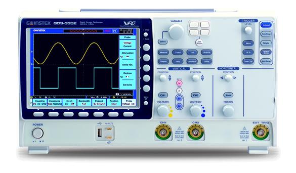


The GDS-3000 series employs VPO (Visual Persistence Oscilloscope) signal processing technology to improve the efficiency of waveform display capability with a high-speed waveform update rate and multi-level afterglow display.
The GDS-3000 series is designed with a high-speed FPGA parallel processing mode instead of the traditional microprocessor architecture, which greatly improves the data processing speed and waveform acquisition rate. The VPO technology enables the GDS-3000 series to display the frequency of the test signals in a multi-level afterglow similar to that of analog oscilloscopes. Because VPO technology oscilloscopes display signals that include amplitude, time, and signal strength in a three-dimensional waveform data to show each wave point, the GDS-3000 provides a lot of useful information on the screen compared to traditional digital storage oscilloscopes. High-speed waveform capture technology allows for more accurate analysis of fast events such as video, jitter, noise, and choppy signals.
The GDS-3000 series features a high-speed 5 GSa/s real-time sampling rate and a high-speed 100 GSa/s equivalent time sampling rate for more precise waveform reconstruction of repetitive signals, providing a cost-effective waveform testing solution for the market. The high speed signal acquisition capability along with the VPO signal capture technology makes the GDS-3000 series ideal for observing video, occasional signals and surge events...instantaneous events. Backed by the GDS-3000 series' powerful technology, you can have full confidence in every complex signal acquisition process.
The GDS-3000 series adopts VPO (Visual Persistence Oscilloscope) signal processing technology to improve the performance of waveform display capability with high speed waveform update rate and multi-layer afterglow display.The design of GDS-3000 series adopts high-speed FPGA parallel processing mode instead of the traditional microprocessor architecture, which greatly improves the data processing speed and waveform acquisition rate. The VPO technology enables the GDS-3000 series to display the frequency of test signals in a multi-level afterglow similar to that of analog oscilloscopes. Because VPO technology oscilloscopes display signals that include amplitude, time, and signal strength in three dimensions, the GDS-3000 provides more useful information on the screen than traditional digital storage oscilloscopes. High-speed waveform capture technology allows for more accurate analysis of fast events such as video, jitter, noise, and choppy signals.
In addition to passive probes, the GDS-3000 series can also be equipped with differential or current probes for additional test applications. Three 25MHz, 50MHz, and 100MHz differential probes, and two new 50MHz/30A and 100MHz/30A current probes are available with the GDS-3000 to provide a total solution for a wide range of power test applications.
Comparison of GDS-3000 Series VPO Digital Storage Oscilloscopes and Tektronix's TDS-3000http://v.youku.com/v_show/id_XMjQzNzI0NjY4.html?spm=a2hzp.8253869.0.0
GDS-3000 Series VPO Digital Storage Oscilloscopes Unique Window Split Functionhttp://v.youku.com/v_show/id_XMjQzNzI1MDYw.html?spm=a2hzp.8253869.0.0
GDS-3000 Series VPO Digital Storage Oscilloscopes Introductionhttp://v.youku.com/v_show/id_XMjQzNjc5MzU2.html?spm=a2hzp.8253869.0.0
GDS-3000 Series VPO Digital Storage Oscilloscopes VPO Technology Introductionhttp://v.youku.com/v_show/id_XMjQzNzExMDEy.html?spm=a2hzp.8253869.0.0
Goodwell Digital Oscilloscopes Product Sharinghttps://v.youku.com/v_show/id_XNDYxNDE4NDgzNg==.html
Quick Selection
| model number | bandwidths | sampling rate | Storage depth | channel number | Standard Interface |
| GDS-3152 | 150MHz | 2.5GSa/s | 25K per channel | 2 | USB/LAN/RS232,GPIB Option |
| GDS-3154 | 150MHz | 5GSa/s | 25K per channel | 4 | USB/LAN/RS232,GPIB Option |
| GDS-3252 | 250MHz | 2.5GSa/s | 25K per channel | 2 | USB/LAN/RS232,GPIB Option |
| GDS-3254 | 250MHz | 5GSa/s | 25K per channel | 4 | USB/LAN/RS232,GPIB Option |
| GDS-3352 | 350MHz | 5GSa/s | 25K per channel | 2 | USB/LAN/RS232,GPIB Option |
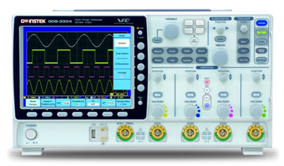
| GDS-3354 | 350MHz | 5GSa/s | 25K per channel | 4 | USB/LAN/RS232,GPIB Option |
| GDS-3502 | 500MHz | 4GSa/s | 25K per channel | 2 | USB/LAN/RS232,GPIB Option |
| GDS-3504 | 500MHz | 4GSa/s | 25K per channel | 4 | USB/LAN/RS232,GPIB Option |
| Detailed specifications | ||||||||
| GDS- 3152 | GDS- 3154 | GDS- 3252 | GDS-3254 | GDS- 3352 | GDS- 3354 | GDS- 3502 | GDS- 3504 | |
| vertical system | ||||||||
| input channel | 2Ch+EXT | 4Ch+EXT | 2Ch+EXT | 4Ch+EXT | 2Ch+EXT | 4Ch+EXT | 2Ch+EXT | 4Ch+EXT |
| bandwidths | DC~150MHz(-3dB) | DC~250MHz(-3dB) | DC~350MHz(-3dB) | DC~500MHz(-3dB) | ||||
| rising time | 2.3ns | 1.4ns | 1ns | 700ps | ||||
| vertical resolution | 8 bit | |||||||
| Vertical Resolution (1MΩ) | 2mV ~ 5V/div | |||||||
| Vertical resolution 50/75Ω | 2mV ~ 1V/div | |||||||
| Input coupling | AC, DC, GND | |||||||
| Input impedance | 1MΩ / / 15pF | |||||||
| DC Gain Accuracy | ±(3%X |Reading| + 0.1div+ 1mV) | |||||||
| polarities | Forward, reverse | |||||||
| Maximum input impedance (1MΩ) | 300V (DC+AC peak), CAT I | |||||||
| Maximum input voltage (75/ 50Ω) | 5 Vrms, CAT I | |||||||
| offset range | 2mV/div ~ 100mV/div: ±0.5V; 200mV/div ~ 5V/div: ±25V | |||||||
| bandwidth limit | 20 MHz | 20/100MHz | 20/100/200MHz | 20/100/200/350MHz | ||||
| Waveform Signal Processing | Add, subtract, multiply, divide, FFT, FFTrms | |||||||
| trigger system | ||||||||
| source (of information etc) | Dual Channel: CH1, CH2, Line, Ext ; Quad Channel: CH1, CH2, CH3, CH4, Line, Ext | |||||||
| Trigger Mode | Auto Mode (Rolling Mode is available to measure signals 100 ms/div or slower), Normal Mode, One Shot Mode | |||||||
| Trigger Type | Edge, Pulse Width, Video, Dwarf Wave, Rise and Fall, Event Delay, (1 ~ 65, 535 events), Time Delay (10nS~10S) I2C, SPI, UART (optional) | |||||||
| Trigger delay range | 10ns ~ 10 S | |||||||
| Coupling Options | AC, DC, LF rej, HF rej, Noise rej | |||||||
| (level of) sensitivity | DC~50MHz approx. 1div or 1.0mV; 50MHz~150MHz approx. 1.5div or 15mV; 150MHz~350MHz approx. 2div or 20mV | |||||||
| external trigger | ||||||||
| realm | ±15V | |||||||
| (level of) sensitivity | DC ~ 150 MHz pprox. 100mV ;150 MHz ~ 250 MHz approx. 150mV;250 MHz ~ 350 MHz approx. 150mV;350 MHz ~ 500 MHz approx. 200mV | |||||||
| Input Impedance | 1MΩ ± 3%, ~ 16pF | |||||||
| Horizontal system | ||||||||
| realm | 1ns/div~100s/div (1-2-5 increments ;GDS-3502/3504: 1-2.5-5 increments); ROLL: 100ms/div~100s/div | |||||||
| pre-trigger | Maximum 10div per cell | |||||||
| post-trigger | 1000div | |||||||
| precision | Accuracy ± 20 ppm , ≧1 ms time interval | |||||||
| signal acquisition system | ||||||||
| real time sampling rate | 2.5GSa /s | 5GSa/s | 2.5GSa/s | 5GSa/s | 5GSa/s | 5GSa/s | 4GSa/s | 4GSa/s |
| equivalent sampling rate | Up to 100 GSa/s | |||||||
| Record length | 25 k points | |||||||
| Capture Mode | General: sample values captured; Average: waveform averaging from 2 to 256; Peak Detection: captures bursts at a narrow frequency scan rate of 2 ns; High Resolution: real-time magazine averaging reduces random noise and increases vertical resolution | |||||||
| X-Y Mode | ||||||||
| X-axis input | Channel 1; Channel 3 | |||||||
| Y-axis input | Channel 2; Channel 4 | |||||||
| phase displacement | ± 3 ° at 100 kHz | |||||||
| Cursors and measuring systems | ||||||||
| cursor (computing) (Taiwan) | Amplitude and time parameters can be captured and limited. | |||||||
| automatic measurement | 28organizeVpp, Vamp, Vavg, Vrms, Vhi, Vlo, Vmax, Vmin, Rise Preshoot/Overshoot, Fall Preshoot/Overshoot, Freq, Period, Rise Time, Fall Time, Positive Width, Negative Width, Duty Cycle, Phase, and 8 Delay Measurement Functions (FRR, FRF, FFR, FFF, LRR, LRF, LFR, LFF). Negative Width, Duty Cycle, Phase, and 8 delay measurement functions (FRR, FRF, FFR, FFF, LRR, LRF, LFR, LFF). | |||||||
| vernier measurement | Voltage difference (∆V) Time difference (∆T) | |||||||
| automatic counting | 6-digit frequency counter from 2 Hz to rated frequency | |||||||
| Power measurement (optional) | ||||||||
| Power Quality Measurement | VRMS, V Crest Factor, Frequency, IRMS, I Crest Factor, Real Power, Apparent Power, Virtual Power, Power Factor, Phase Angle. | |||||||
| harmonic measurement | Freq, Mag, Mag rms, Phase, THD-F, THD-R, RMS | |||||||
| ripple measurement | Vripple Iripple | |||||||
| inrush current | First peak, second peak | |||||||
| Control Board Functions | ||||||||
| Autoset | Single button, automatic installation program, all vertical and horizontal piping and triggering systems, undo autoset | |||||||
| Automatic range | Allows the user to move quickly from test point to test point without having to reset the oscilloscope test points for each test point | |||||||
| Save Settings | 20 groups | |||||||
| Save Waveforms | 24 groups | |||||||
| Display System | ||||||||
| TFT LCD | 8" TFT LCD SVGA color display (LED backlight) | |||||||
| Display resolution | Vertical 800 × Horizontal 600 (SVGA) | |||||||
| interpolation | Sin(x)/x and equivalent time sampling | |||||||
| waveform display | Points, vectors, persistence of variables, persistence of infinity | |||||||
| Display Grid | 8 x 10 divisions | |||||||
| display brightness | tunable | |||||||
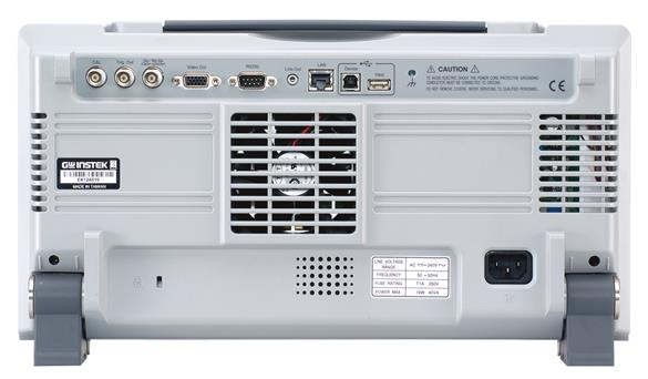
| interfaces | ||||||||
| Rs-232 C Port | DB-9port | |||||||
| USB Port | 2 set USB 2.0 Hi-Speed Host Port ; 1 set USB 2.0 Hi-Speed Device Port | |||||||
| Ethernet | RJ-45 port, 10/100Mbps | |||||||
| VGAVideoPort | DB-15port, SVGA monitor output | |||||||
| line output | 3.5mm Stereo Output Connector / Go/NoGo Audio Alarm Output | |||||||
| GPIB (Optional) | USB GPIB Interface Converter | |||||||
| Go/NoGo BNC | Maximum 5V /10mA TTL open outputs | |||||||
| Kensington Style Lock | Rear panel security lock slot attaches to standard Kensington style locks | |||||||
| power supply | ||||||||
| voltage range | AC 100V ~ 240V, 48 Hz ~ 63 Hz, automatic selection | |||||||
| (sth. or sb) else | ||||||||
| Multi-language menu | usability | |||||||
| Online Help | usability | |||||||
| clocks | Time and data, providing data/time for saving data | |||||||
| Size and weight | 400(W) x 200(H) x 130(D), approx. 4 kg. | |||||||
One manual, one power cord
GTP-151R: 150MHz (10:1) passive probe for GDS-3152/ 3154 (one per channel)
GTP-251R: 250MHz (10:1) passive probe for GDS-3252/ 3254 (one per channel)
GTP-351R: 350MHz (10:1) passive probe for GDS-3352/ 3354 (one per channel)
GTP-501R: 500MHz (10:1) passive probe for GDS-3502/ 3504 (one per channel)
Optional Accessories
GTC-001 Equipment Cart, 450(W) x 430(D)mm (120V Input Socket)
GTC-002 Equipment Cart, 330(W) x 430(D)mm (120V Input Socket)
GTL-110 Test Leads, BNC to BNC Connector Leads
GTL-232 RS-232C Cable, 9-pin Female to 9-pin Female, Null Modem for computer
GTL-242 USB 1.1 Cable, Type A-B, 4P, 1800mm
differential probe
GDP-025: 25MHz High Voltage Differential Probe
GDP-050: 50MHz High Voltage Differential Probe
GDP-100: 100MHz High Voltage Differential Probe
current probe
GCP-530: 50MHz/ 30A Current Probe
GCP-1030: 100MHz/ 30A Current Probe
GCP-206P: Power supply to support current probe (2 input channels)
GCP-425P: Power supply to support current probes (4 input channels)
Ordering Information
GDS-3152 150MHz, 2-Channel, Color LCD Display Digital Storage Oscilloscope
GDS-3154 150MHz, 4-Channel, Color LCD Display Digital Storage Oscilloscope
GDS-3252 250MHz, 2-Channel, Color LCD Display Digital Storage Oscilloscope
GDS-3254 250MHz, 4-Channel, Color LCD Display Digital Storage Oscilloscope
GDS-3352 350MHz, 2-Channel, Color LCD Display Digital Storage Oscilloscope
GDS-3354 350MHz, 4-Channel, Color LCD Display Digital Storage Oscilloscope
GDS-3502 500MHz, 2-Channel, Color LCD Display Digital Storage Oscilloscope
GDS-3504 500MHz, 4-Channel, Color LCD Display Digital Storage Oscilloscope
optional
GUG-001 GPIB to USB Adapter
DS3-SBD Serial Bus Measurement Software: I2C / SPI / UART (4-channel model only)
DS3-PWR Power Measurement Software: Power Quality Measurement / Harmonic Measurement / Ripple Measurement (In-rush current)


