I-V Characterization of Field Effect Tube (MOSFET)
Specialized in semiconductor electrical testing
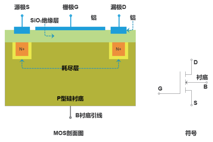
MOSFET (Metal-Oxide Semiconductor Field Effect Transistor) is a common semiconductor device that utilizes the electric field effect to control the amount of current, and is widely used in analog and digital circuits. MOSFETs can be made of silicon, graphene, carbon nanotubes and other materials, and are a hot topic in materials and device research. The main parameters are input/output characteristic curve, threshold voltage VGS(th), leakage current IGSS, IDSS, breakdown voltage VDSS, low-frequency interconductance gm, output resistance RDS, etc. The MOSFETs are widely used in analog and digital circuits.
Due to the structure of the device itself, it is common for researchers or test engineers in the laboratory to encounter the following test challenges.
(1) Since MOSFETs are multi-port devices, multiple measurement modules are required for collaborative testing. Moreover, the dynamic current range of MOSFETs is large, and a wide range is required for testing, so the ranges of the measurement modules need to be able to be switched automatically;
(2) Gate oxygen leakage and gate oxygen quality is very much related to the increase in leakage to a certain extent can constitute a breakdown, resulting in device failure, so the leakage current of the MOSFET is as small as possible, the better, and need to be tested with high-precision equipment;
(3) As the feature size of MOSFETs becomes smaller and more powerful, the self-heating effect becomes an important factor affecting their reliability. Pulse testing can reduce the self-heating effect, and I-V testing of MOSFETs in pulse mode can accurately evaluate and characterize their properties;
(4) The capacitance test of MOSFET is very important and closely related to its application at high frequency. The C-V curves are different at different frequencies, and it is necessary to conduct C-V tests at multiple frequencies and voltages to characterize the capacitance properties of MOSFETs.
The common parameters of MOSFETs are tested by using Purcell S series high-precision digital source meters and P series high-precision benchtop pulse source meters.
Input/Output Characterization Test
MOSFET is a gate voltage control source drain current device, in a fixed drain voltage, can be measured under a IDs ~ VGs relationship curve, corresponding to a set of stepped drain voltage can be measured a cluster of DC input characteristics curve. The IDS~VDS relationship obtained by MOSFET at a fixed gate voltage is the DC output characteristic, and a cluster of output characteristics can be measured corresponding to a set of stepped gate voltages. Depending on the application scenario, the power specification of MOSFET devices varies. For MOSFET devices below 1A, we recommend two S-series source meters, with a maximum voltage of 300V, a maximum current of 1A, and a minimum current of 100pA, to meet the needs of low-power MOSFET testing.
For MOSFET power devices with maximum currents of 1A~10A, it is recommended to set up a test program with two P-series pulse source meters with a maximum voltage of 300V and a maximum current of 10A.
For MOSFET power devices with a maximum current of 10A~100A, it is recommended to use the P series pulse source meter + HCP to build a test program with a maximum current of up to 100A.
Threshold voltage VGS (th)
VGS(th) is the value of VG S at which the gate source voltage enables the drain to begin to have current; the test instrumentation is recommended for S-series source meters.
Leakage Current Test
IGSS (Gate Source Leakage Current) is the leakage current flowing through the gate at a specific gate voltage; IDSS (Zero Gate Voltage Drain Current) is the leakage current between DS at a specified VDS when VGS=0. It is recommended to use a Purchase S-Series or P-Series Source Meter for this test;
Pressure resistance test
VDSS (drain-source breakdown voltage): It refers to the VDS value when the ID starts to increase dramatically during the process of increasing the drain-source voltage under the condition of VGS=0. According to the different specifications of the devices, their voltage withstand indexes are also inconsistent, and the instruments required for the test are also different, and the S series desktop source meters or P series pulse source meters are recommended for the devices with a breakdown voltage below 300V and a breakdown voltage above 300V, and the E series is recommended for the devices with a maximum voltage of 3500V. For devices with a breakdown voltage of 300V or more, we recommend using the E series with a maximum voltage of 3500V.
C-V Testing
C-V measurements are often used to regularly monitor the manufacturing process of integrated circuits. By measuring the C-V curves of MOS capacitors at high and low frequencies, parameters such as the gate oxide thickness, tox, oxide charge and interface density of states, Dit, flat-band voltage, Vfb, and doping concentration in the silicon substrate can be obtained. Ciss (input capacitance), Coss (output capacitance), and Crss (reverse transfer capacitance) are measured.
If you need to get the detailed system construction plan and test line connection guide, welcome to call us for consultation!
Contact Us
ABOUT US
Dedicated customer line:
13717737785
Business Negotiations:
18929381667
Contact Email:
fp@szwanbo.com
WeChat Customer Service:
Contact our technical support specialists
In order for us to serve you better, please leave your valuable information.
If you need to purchase a specific model, you can filter the product center to select the model and submit an inquiry, fill in the specific number of products, our account manager will immediately give you the most favorable wholesale price!
If you don't find a model you can leave a comment here and we'll do our best to find it for you!


 Comprehensive test and measurement service provider-Shenzhen Weike Electronic Technology Co.


