 Comprehensive test and measurement service provider-Shenzhen Weike Electronic Technology Co.
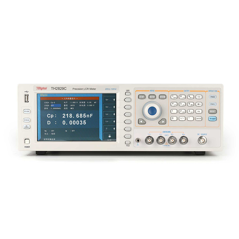


With strong impedance test technology and rich R&D experience, Tonghui keeps launching new impedance test products --- TH2829 series automatic component analyzer is another masterpiece newly launched by our company.
TH2829 series automatic component analyzer applies high-speed processor and new software system, which gives it higher test speed, more comprehensive analysis functions and friendly human-machine interaction experience. The well-designed measurement circuit and optimized algorithm further enhance the test stability of low D-value capacitors and high Q-value inductors. The 10V AC test level, 10V/100mA bias power supply and independent 10V/50mA DC power supply provided by the instrument make it more convenient to apply the instrument to the testing of various passive/active devices. Dual primary and secondary parameter displays, enhanced display system design, up to 201-point list scanning, and graphical analysis capability for a wide range of parameters enable the instrument to meet the most demanding user applications.
Thanks to the application of new generation processor, the instrument has more powerful data processing capability, and the test results can be conveniently stored in the U disk or uploaded to the upper PC or network through a variety of interfaces, to promote the test automation and improve the test efficiency. This series of test frequency up to: 20Hz-1MHz, with a test accuracy of 0.05%, the highest test speed of 9ms / times. The instrument is equipped with HANDLER, USB, LAN, RS232C, DCI, GPIB (optional) and other rich interfaces, all show the rich resources, will bring customers a better cost-effective experience.
The TH2829 series of component analyzers are perfectly suited to the test requirements of a wide range of industrial and military standards.

Functional Features
A. Simultaneous measurement and display of multiple parameters
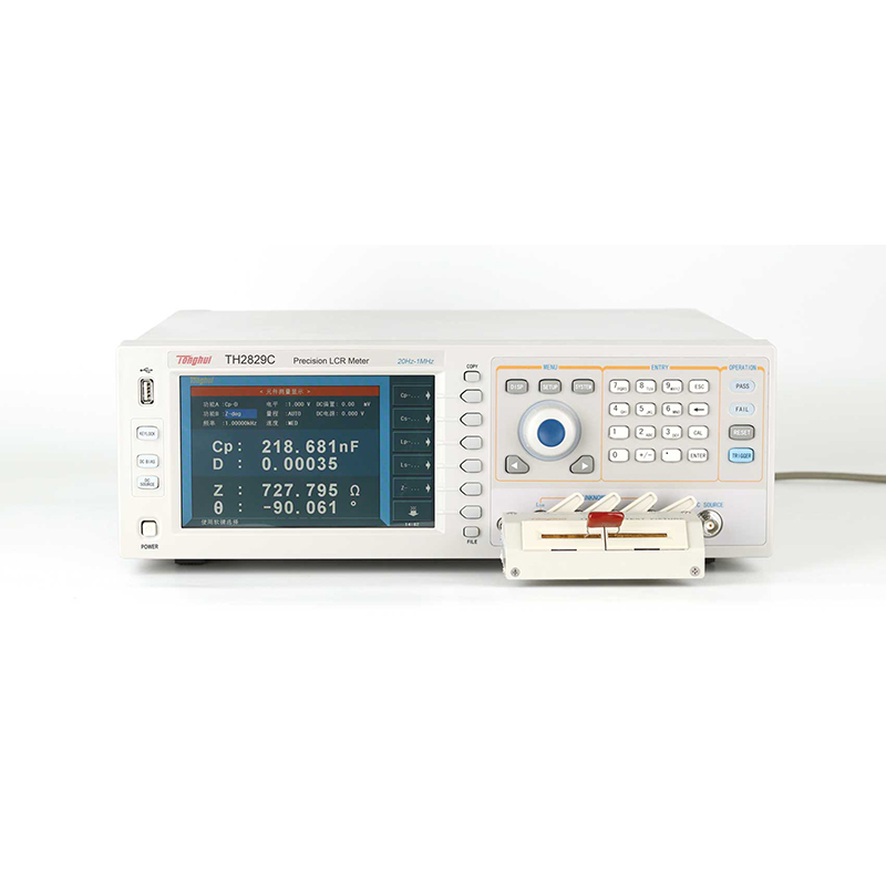
The TH2829 series digital bridge can simultaneously measure four parameters of the impedance element in one test cycle, including two main parameters and two subparameters, and display the test values of the four parameters in the same interface at the same time.


B. High stability and consistency

C. High speed

D. Functions and interfaces


E. Material dielectric constant testing
Together with the special material test fixture TH26077 and the software of the upper computer, it can easily and accurately measure the dielectric constant of materials at different frequencies.

F. Optional accessories


A. Host computer software
a) Generic host computer software
Test approach:

File Save:

Hardware connection: RS232C, USB, GPIB, LAN
Data image saving format: TXT, XLS, MDB, CSV, BMP, JPG, PNG
Other functions: automatic recording, setting file saving, user management, etc.
b) Piezoelectric ceramics host computer software
Analyze the settings:

Analyze the results:

| model number | TH2829A | TH2829C | ||
| monitor (computer) | 800×RGB×480 7-inch TFT LCD monitor | |||
| test signal | frequency | 20Hz-300kHz | 20Hz-1MHz | |
| minimum resolution | 1mHz, 5-bit frequency input | |||
| accuracy | 0.01% | |||
| AC level | Test Signal Voltage Range | 5mV-10Vrms | ||
| Voltage Minimum Resolution | 100μV, 3-bit input | |||
| accuracy | ALC ON | 10% x set voltage + 2mV | ||
| ALC OFF | 6% x set voltage + 2mV | |||
| Test signal current range | 50μA-100mA | |||
| Current Minimum Resolution | 1μA, 3-bit input | |||
| accuracy | ALC ON | 10% x set current + 20μA | ||
| ALC OFF | 6% x set voltage + 20μA | |||
| DC Bias Voltage Source | Voltage / Current Range | 0V- ±10V / 0mA-±100mA | ||
| resolution (of a photo) | 0.5mV / 5μA | |||
| Voltage Accuracy | 1% x set voltage + 5mV | |||
| ISO ON | For inductor, transformer plus bias test | |||
| AC source internal resistance | ISO ON | 100Ω | ||
| ISO OFF | 30Ω, 50Ω, 100Ω selectable | |||
| DCR Source Internal Resistance | 30Ω, 50Ω, 100Ω selectable | |||
| DC Voltage Source | Voltage / Current Range | 0V- ±10V / 0mA-±50mA | ||
| resolution (of a photo) | 1mV | |||
| Voltage Accuracy | 1% x set voltage + 5mV | |||
| output resistance | 100Ω | |||
| LCR Test Parameters | |Z|, |Y|, C, L, X, B, R, G, D, Q, θ, DCR, Vdc-Idc | |||
| Test page parameter display | Two groups of primary and secondary parameters, the second group of parameters can be ON/OFF; a variety of parameters continuous scanning graphic analysis | |||
| Basic Measurement Accuracy | LCR Test Parameters | 0.05% | ||
| calibration condition | Warm-up time: ≥30 minutes; Ambient temperature: 23±5oC; Signal voltage: 0.3Vrms-1Vrms; Clear "0": after OPEN, SHORT; Test cable length: 0 m | |||
| Measurement time (≥10 kHz) | Fast: 9 ms/times Medium: 67 ms/times Slow: 187 ms/times plus display character refresh time | |||
| LCR parameter display range | | z | , r , x , dcr | 0.00001Ω - 99.9999MΩ | ||
| |Y|, G, B | 0.00001μs - 99.9999s | |||
| C | 0.00001pF - 9.99999F | |||
| L | 0.00001μH - 99.9999kH | |||
| D | 0.00001 - 9.99999 | |||
| Q | 0.00001 - 99999.9 | |||
| θ (DEG) | -179.999o - 179.999o | |||
| θ (RAD) | -3.14159 - 3.14159 | |||
| Δ% | -999.999% - 999.999% | |||
| equivalent circuit | Series, Parallel | |||
| Measurement range | Automatic, Hold | |||
| trigger method | Internal, Manual, External, Bus | |||
| Average number of times | 1-256 | |||
| calibration function | Open Circuit, Short Circuit Full Frequency, Spot Frequency Calibration, Load Calibration | |||
| mathematical operation | Direct reading, ΔABS, Δ% | |||
| Delay time setting | 0 -- 999, minimum resolution 100us | |||
|
Comparator Functions
|
10-speed binning, BIN1 to BIN9, NG, AUX | |||
| stall counting function | ||||
| PASS, FAIL front panel LED display | ||||
| List Scanning | -Up to 201 point list scan with separate list scan tests for frequency, AC voltage/current, internal/external DC bias voltage/current, and independent DC source voltage. Each scan point can be sorted individually. The second scan parameter can be selected at the same time, but cannot be the same as the first scan parameter. | |||
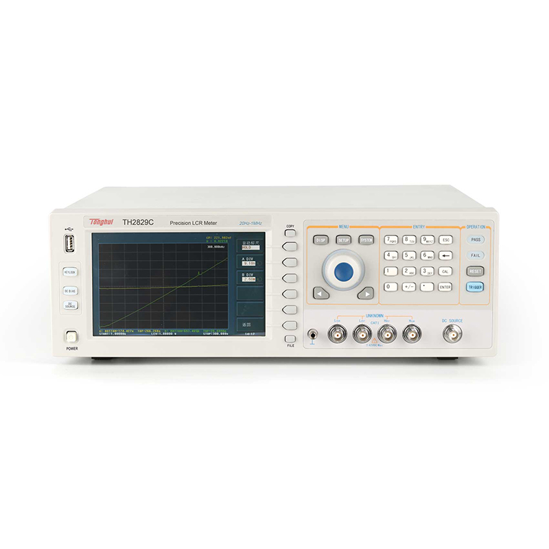
| graphical analysis | -Graphical scanning analysis of frequency, AC level, DC bias, etc. is available.
-Set the scanning start point, end point, and the number of points per scan. -Display maximum and minimum values, and read the value of any selected scan point. -Scanned graphics can be stored on the instrument's internal or external USB memory. |
|||
| internal non-volatile memory | 100 sets of LCRZ instrument setting file memory | |||
| External USB memory | GIF image, CSV data file LCRZ instrument setting file memory test data USB memory direct storage | |||
| connector | 1A bias current source | 1A DC bias current source internally mountable (option) | ||
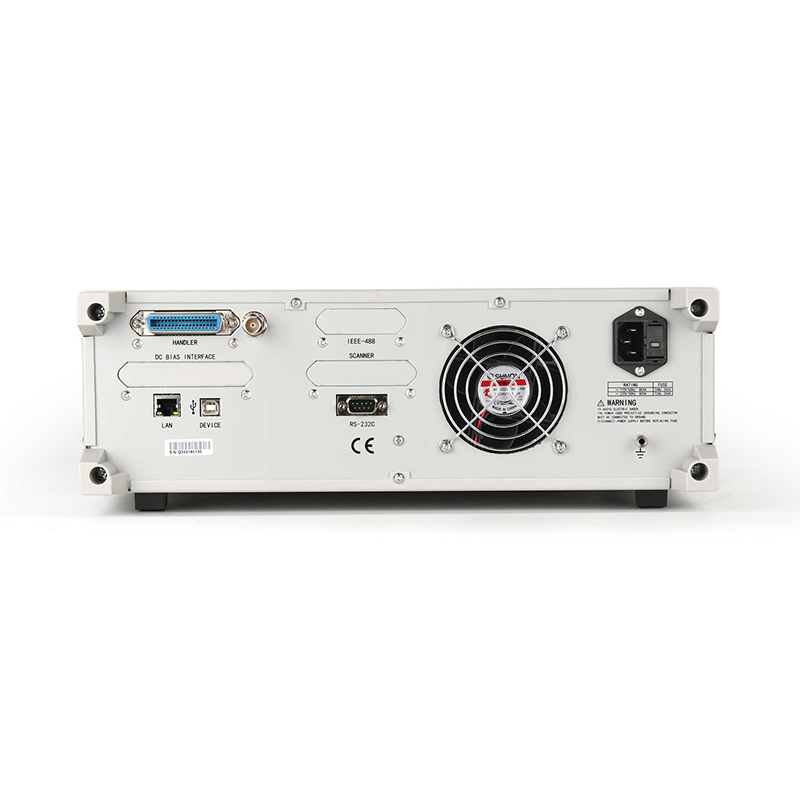
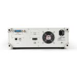
| I/O Interface | HANDLER, output from the rear panel of the instrument | |||
| serial communications interface | USB, RS232C | |||
| Parallel Communication Interface | GPIB interface (option) | |||
| network interface | LAN | |||
| memory interface | USB HOST (front panel) | |||
| General technical parameters | ||||
| Operating Temperature, Humidity | 0℃-40℃, ≤ 90%RH | |||
| Power Requirements | input voltage | 99V-121V, 198V-242V AC | ||
| frequency | 47Hz-63Hz | |||
| power wastage | Maximum 80VA | |||
| Volume(W×H×D) | 400mm × 132mm × 385mm | |||
| weights | Approx. 13 kg | |||
Basic accuracy factor curve:

Note: Test signal level: 0.3Vrms - 1Vrms
The upper values (those without parentheses) apply to medium and slow speeds, and the lower values (those in parentheses) apply to fast speeds.
■ Measurement frequency: 20Hz-1MHz, resolution: 1mHz
■ Basic accuracy: 0.05%
■ Test speed: 9ms/time
■ Impedance analysis and testing of piezoelectric ceramics, ultrasonic transducers and other devices
■ Continuous curve scanning/graphic analysis function
■ Simultaneous display of four measurement parameters
■ 800 x RGB x 480 7-inch TFT LCD monitor
■ Built-in 100 sets of LCRZ setting files
■ Direct storage of GIF images, CSV data files in USB memory
■ HANDLER, USB, LAN, RS232C, GPIB (optional) DCI interface
■ Signal source selection 10V/100mA programmable AC test level
■ 10V/100mA programmable DC bias power supply 10V/50mA standalone DC voltage source
■ 1A DC bias current source (optional) 120A external bias current source (optional)
■ Up to 201-point list scanning
■ Passive Components.
Evaluation of impedance parameters and performance analysis of capacitors, inductors, cores, resistors, piezoelectric devices, transformers, chip assemblies, and network components, etc.
■ Semiconductors.
Test and analysis of parasitic parameters of LED driver integrated circuits; C-VDC characteristics of varactor diodes; analysis of parasitic parameters of transistors or integrated circuits
■ Other components.
Impedance evaluation of printed circuit boards, relays, switches, cables, batteries, etc.
■ Media Material.
Evaluation of dielectric constants and loss angles of plastics, ceramics and other materials
■ Magnetic material.
Evaluation of permeability and loss angle of ferrites, amorphous and other magnetic materials
■ Semiconductor materials.
Dielectric constant, conductivity and C-V properties of semiconductor materialsLiquid crystal materials: C-V properties of liquid crystal units such as dielectric constant and elasticity constant

| standard equipment | |||||
| Accessory Name | model number | ||||
| fixture (machining) | TH26048 | ||||
| short circuit board | TH26010 | ||||
| Boxed Four-Ended Insulated Locking Kelvin Test Leads | TH26011BS | ||||
Recommended


