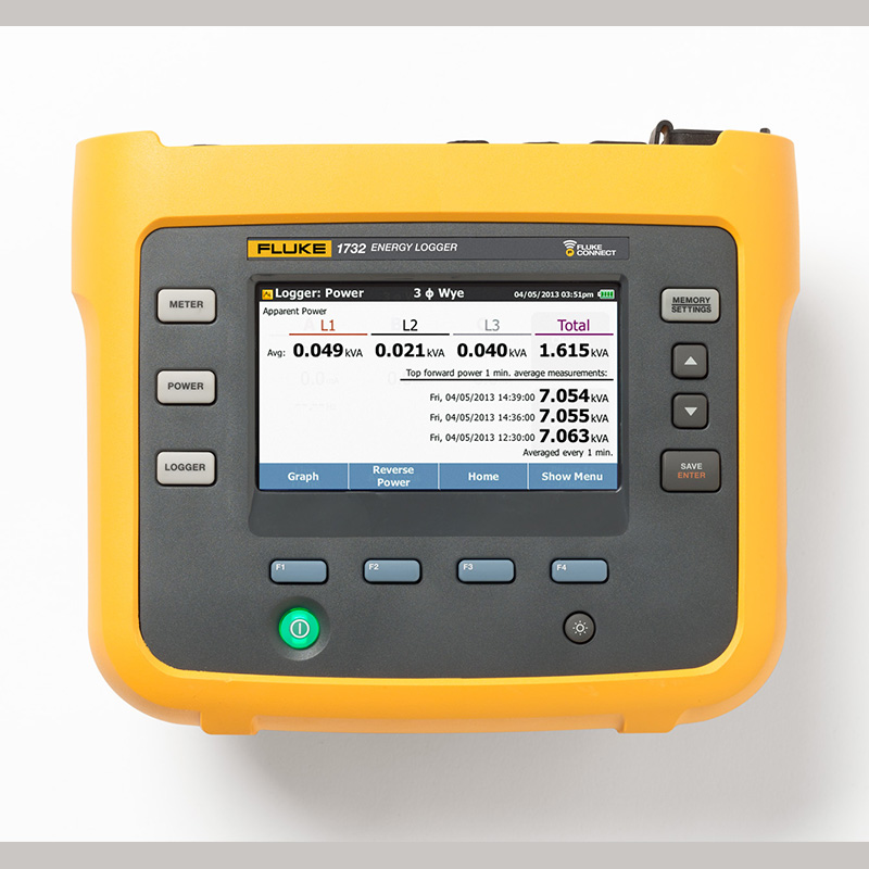
Product Overview: Fluke 1760 Three-Phase Power Quality Recorder
Meets the extremely stringent Class A standards for power quality testing
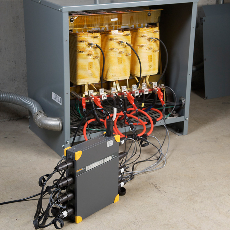
The Fluke 1760 Three-Phase Power Quality Recorder is fully compliant with IEC 61000-4-30 Class A, making it ideal for advanced power quality analysis and harmonized standards testing. Designed to analyze utility and industrial distribution systems in low and medium voltage grids, this power quality monitoring tool allows users the flexibility to customize thresholds, algorithms and measurement options. The 1760 Power Logger captures detailed information on user-selected parameters.
appliance
Detailed interference analysis - Perform fast transient analysis to identify the root cause of equipment failures for future improvements and preventive maintenance. The fast transient option and 6000 V range make it possible to capture very brief pulses (e.g., lightning strikes).
Compliance with level A quality of service requirements - Verify power quality at the inlet. With Class A standard certification, the Fluke 1760 allows for a variety of rigorous verifications.
Event correlation at multiple locations - With GPS time synchronization, users can quickly detect where the first failure occurs (inside or outside the facility).
Galvanic isolation and DC coupling - Allows comprehensive measurements of different electrical energy systems. For example, troubleshooting UPS systems by synchronizing the recording of battery voltage and power output.
Power quality and power load analysis - Evaluate basic power quality prior to installation to ensure compliance with critical system requirements; and Verify power system capacity prior to adding loads.
Product Specifications: Fluke 1760 Three-Phase Power Quality Recorder
| Overview of measurement functions | ||
| Statistical assessment | Power quality statistics in accordance with EN50160 and DISDIP tables such as ITIC, CEBEMA and ANSI. | |
| Event List | Voltage dips, surges and interruptions are detected and stored in the event list. Also, any activated trigger generates an event that is added to this list. | |
| The event list shows the exact time of the event, as well as its duration and magnitude. The events can be categorized according to several attributes and selected for further root cause analysis. | ||
| If the trigger is activated, true valid (RMS) values, transients, and fast transients can be stored. | ||
| continuous recording | The Fluke 1760 records the RMS values and corresponding minimum and maximum values for the following parameters: - voltage - electric current - Electricity P, Q, S - power factor - kWh - flicker - disequilibrium - frequency - Harmonic/interharmonic continuity is accumulated using the following times: day, 10 minutes, free interval, e.g. 15 minutes, 2 hours. |
|
| trigger record | effective value | The accumulation time can be adjusted between 10 ms (1/2 cycle), 20 ms (1 cycle), 200 ms (10/12 cycles), or 3 sec (150/180 cycles). |
| RMS values, harmonics and interharmonics are calculated in synchronization with the power supply frequency. | ||
| Harmonics and interharmonics with a fundamental accumulation time of 200 ms | ||
| Sampling rate of 10.24 kHz for all 8 channels | ||
| power signal (of an electrical device etc) | Phase and N Lead, Voltage and Current | |
| online mode | Variable Refresh Rate. This feature allows users to verify meter settings and quickly navigate through oscilloscopes, transients and events. | |
| General data | ||
| intrinsic uncertainty | Please refer to the reference conditions, which provide a two-year guarantee | |
| quality system | Developed and manufactured according to ISO 9001: 2000 | |
| environmental conditions | Operating temperature range | 0 °C to +50 °C; 32 °F to +122 °F |
| Operating Temperature Range | -20 °C to +50 °C; -4 °F to +122 °F | |
| Storage temperature range | 20 °C to +60 °C; -4 °F to 140 °F | |
| reference temperature | 23 °C ±2 K; 74 °F ±2 K | |
| climatic scale | B2 (IEC 654-1), -20°C to +50°C; -4°F to +122°F | |
| Maximum working altitude | 2000 m: max. 600 V CAT IV¹ Power supply: 300 V CAT III 5000 m: max. 600 V CAT III¹ Power supply: 300 V CAT II |
|
| 1. Depending on the sensor | ||
| reference condition | environmental temperature | 23 °C ±2 K; 74 °F ±2 K |
| power supply | 230 V ±10% | |
| power frequency | 50 Hz / 60 Hz | |
| code | Nominal input voltage indicated Udin | |
| on average | 10-minute intervals | |
| housings | Insulated, rugged plastic housing | |
| Electromagnetic Compatibility (EMC) | radiation standard | Class A according to IEC/EN 61326-1 |
| immunity | IEC/EN 61326-1 | |
| power supply | range (of scales or measuring equipment) | AC: 83 V to 264 V, 45 to 65 Hz |
| DC: 100 V to 375 V | ||
| security level | IEC/EN 61010-1 2nd edition | |
| 300 V CAT III | ||
| power wastage | NiMH, 7.2 V, 2.7 hours | |
| battery pack | If the power supply fails, the internal battery will continue to supply power for up to 40 minutes. After that, or if the battery is depleted, the Fluke 1760 shuts down; when the supply voltage is restored, measurements can continue using the most recent previous settings. The battery can be replaced by the user. | |
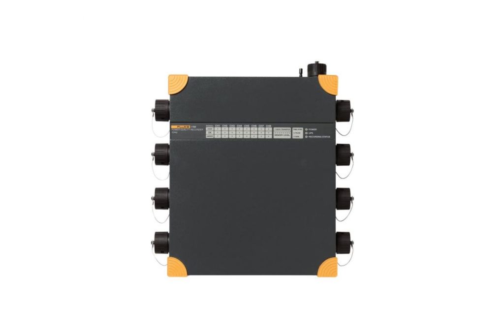
| monitor | The Fluke 1760 is equipped with LEDs that indicate the status of each of the following: 8 channels, phase sequence, power (mains or battery), memory usage, time synchronization, and data transfer. | |
| Power indicator | Long light: the power supply is normally powered. Out: Power is supplied via the internal battery in the event of a power failure. |
|
| A 3-color indicator for each channel is used to indicate | overloaded state underload condition |
|
| data memory | 2 GB flash memory | |
| memory mode | biometrics | |
| connector | Ethernet (100MB/s), Windows® XP, 7 and 8 compatible, RS 232, external modem (via RS 232) | |
| Baud rate for RS 232 | 9600 baud to 115K baud | |
| Dimensions (H x W x D) | 325 x 300 x 65 mm; 2.8 x 11.8 x 2.6 in | |
| weights | Approx. 4.9 kg; 10.8 lbs (without accessories) | |
| warranty period | 2 years | |
| Calibration interval | 1 year for category A, 2 years for others. | |
| signal conditioning | ||
| 50 Hz System Range | 50 Hz ±15% (42.5 Hz to 57.5 Hz) | |
| 60 Hz System Range | 60 Hz ±15% (51 Hz to 69 Hz) | |
| resolution (of a photo) | 16ppm | |
| 50 Hz power supply frequency sampling frequency | 10.24 kHz, sampling rate synchronized with power supply frequency. | |
| Uncertainty of frequency measurements | < 20 ppm | |
| Uncertainty of the internal clock | < 1s/day | |
| Measurement interval | Totalization of interval values according to IEC 61000-4-30 Class-A | |
| Minimum, maximum | 1/2 cycle, e.g. 10 ms RMS value (50Hz) | |
| transient | Sample rate range of 100 kHz to 10 MHz per channel | |
| harmonic (wave with frequency an integer multiple of the fundamental) | Complies with IEC 61000-4-7:2002: 200 ms. | |
| flicker | Conforms to EN 61000-4-15:2003: 10 minutes (Pst), 2 hours (Plt) | |
| Measurement input | ||
| Number of inputs | 8 current-isolated inputs for voltage and current measurement. | |
| Sensor Safety | max. 600 V CAT IV (depending on sensor) | |
| Basic security level | 300 V CAT III | |
| Rated Voltage (rms) | 100 mV | |
| Range (peak) | 280 mV | |
| Overload Capacity (rms) | 1000 V (continuous) | |
| Voltage Rise Rate | 15 kV / µs max. | |
| input resistance | 1 MΩ | |
| Input Capacitance | 5 pF | |
| Input filters | Each channel is equipped with a passive low-pass filter, an anti-mixing filter and a 16-bit A/D converter. All channels are sampled in synchronization with a common quartz control clock pulse. The filter prevents voltage transients and limits the rate of rise of the signal, reducing the high-frequency component, especially in the case of noise voltages exceeding half the A/D converter's sampling rate by 80 dB, and thus realizing very small measurement errors over a very large amplitude range. This is also effective under extreme operating conditions such as transient voltages at the converter output. |
|
| uncertainties | ||
| Uncertainty at reference conditions | Includes voltage sensors with uncertainties according to IEC 61000-4-30 Class-A. All voltage sensors are suitable for DC up to 5 kHz. | |
| Sensor 1000 V | 0.1% Udin = 480 V and 600 V P-N | |
| Sensor 600 V | 0.1% Udin = 230 V P-N | |
| Inherent uncertainty of harmonics | Class I according to EN 61000-4-7:2002 | |
| reference condition | 23°C ± 2 K < 60 % rH; 74°F ± 2 K < 60 % rH | |
| Instrument warm-up > 3 hours | ||
| Power supply: 100 V to 250 V AC | ||
| temperature drift | 100 ppm / K | |
| ageing | < 0.05%/year | |
| Common mode rejection ratio | > 100 dB (at 50 Hz) | |
| temperature drift | Change in increase due to temperature: < 0.005 %/K | |
| ageing | Change in increase due to aging: < 0.04 %/year | |
| noises | Noise voltage, short-circuit input: < 40 µV | |
| direct current (D.C.) | ± (0.2% rdg + 0.1% sensor) | |
Model: Fluke 1760 Three-Phase Power Quality Recorder
FLUKE-1760 US
Topas Power Quality Recorder
With 8 input channels (4 current/4 voltage channels or 8 voltage channels)
Contains.
- Internal flash memory 2 GB
- PQ analysis software included on CD-ROM
- Ethernet cable for network connection (1)
- Cross-linked Ethernet cable for direct connection to PC (1)
- Power Cables (1)
- operation manual
- grip
- 4 voltage probes (600 V for international settings; 1000 V for US settings)
- 4 current probes (dual range flexible current probe 1000 A / 200 A AC)
- GPS time synchronization receivers
 Comprehensive test and measurement service provider-Shenzhen Weike Electronic Technology Co.
