 Comprehensive test and measurement service provider-Shenzhen Weike Electronic Technology Co.
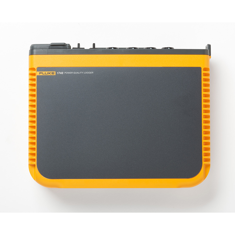
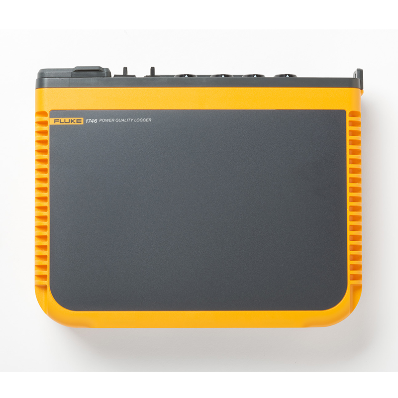

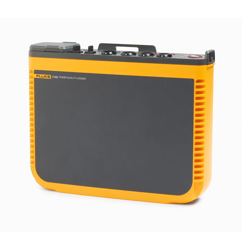

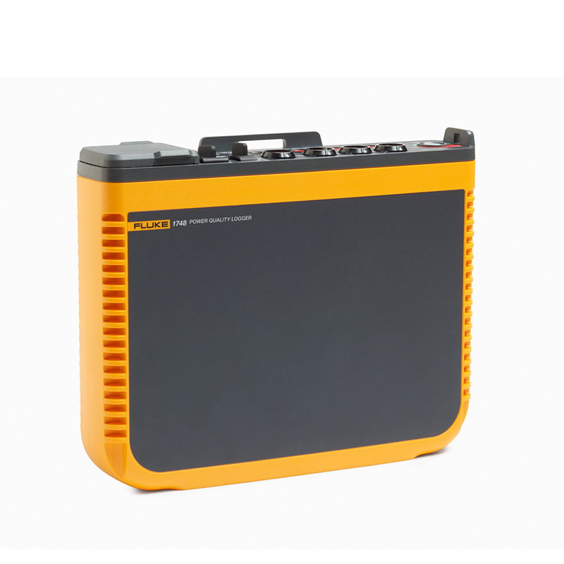


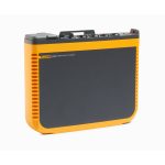


Product Overview: Fluke 1742, 1746 and 1748 Online Removable Power Quality Recorders
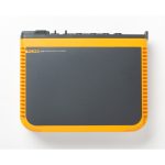
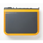
The Fluke 1742, 1746, and 1748 in-line removable power quality recorders provide easy and fast real-time access to the data you need to make important power quality and energy decisions.
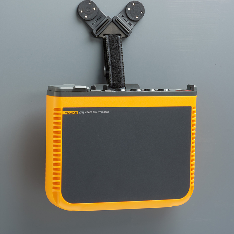
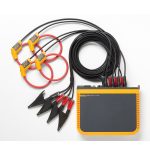
The Fluke 1740 Series of online, removable power quality recorders are compact, rugged, and designed for technicians and engineers who need the flexibility to troubleshoot, quantify energy usage, and analyze power distribution systems. With the ability to record up to 500 parameters simultaneously and capture events, it's easier than ever to identify intermittent or hard-to-find power quality problems. The included Energy Analyze Plus software quickly evaluates power quality at the feeder, substation, or load in accordance with national and international standards such as EN 50160 and IEEE 519.
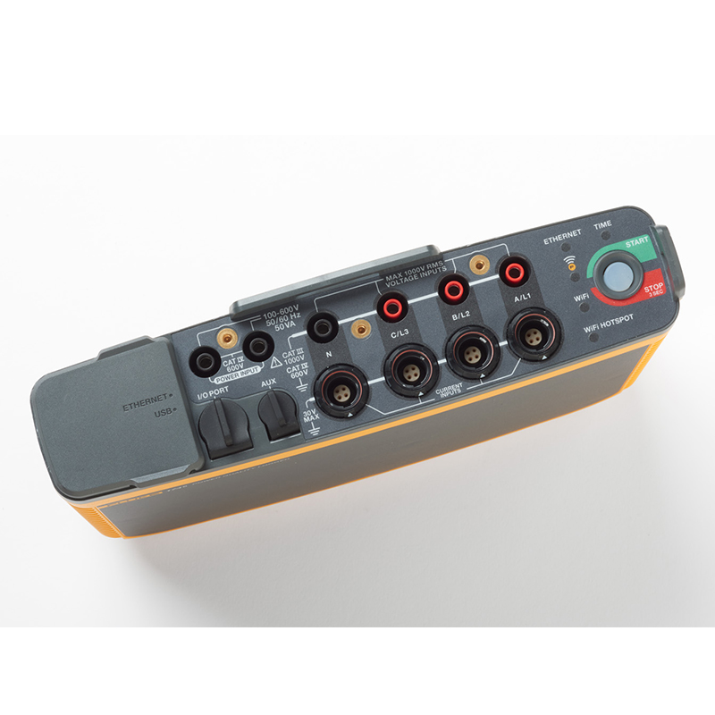
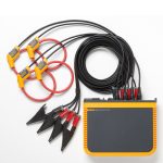
With an optimized user interface, flexible current probe, and smart measurement verification features, you can digitally verify and correct connection errors, making setup easier than ever and reducing measurement uncertainty. Use wireless connectivity (WiFi) to view data directly in the field, minimizing your time spent in potentially hazardous environments and reducing the need to wear personal protective equipment.
The Fluke 1748 can record more than 500 different parameters during each averaging period. This allows you to analyze power quality in detail and correlate events with detailed waveform data to help determine the root cause of disturbances. For basic power quality logging, the Fluke 1746 captures all relevant power parameters for energy conservation studies and grid planning, with an option to upgrade to the 1748. For simple load and energy studies, the Fluke 1742 provides excellent performance in a ruggedized package and can be upgraded to 1746 capability or full 1748 capability.
Which power quality recorder is right for you?
| functionality | Fluke 1742 | Fluke 1746 | Fluke 1748 |
|---|---|---|---|
| functionality | |||
| Voltage, current, power, power factor, frequency | - | - | - |
| Forward/reverse energy | - | - | - |
| peak demand | - | - | - |
| THD | - | - | - |
| flicker | - | - | - |
| Voltage and current harmonics (up to 50th)1 | - | - | |
| disequilibrium1 | - | - | |
| Rapid voltage change events1 | - | - | |
| Interharmonics (up to 50th)1 | - | - | |
| Falling, rising, interrupting and transient event tables1 | - | - | |
| inrush current1 | - | - | |
| Transient (low frequency)/waveform deviation events2 | - | ||
| record (in sports etc) | |||
| tendencies | - | - | - |
| waveform snapshot2 | - | ||
| RMS curve2 | - | ||
| correspond (by letter etc) | |||
| Ethernet | - | - | - |
| USB (mini B) | - | - | - |
| WiFi download (instrument to device) | - | - | - |
| WiFi download via WiFi router (registration required) | selectable | selectable | selectable |
| kit | |||
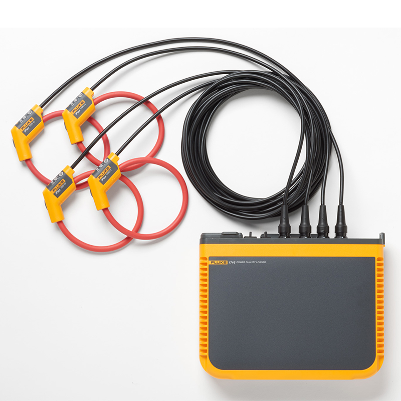
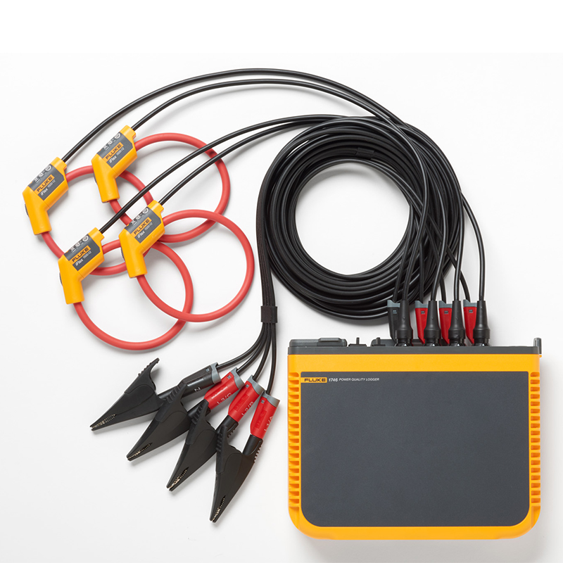
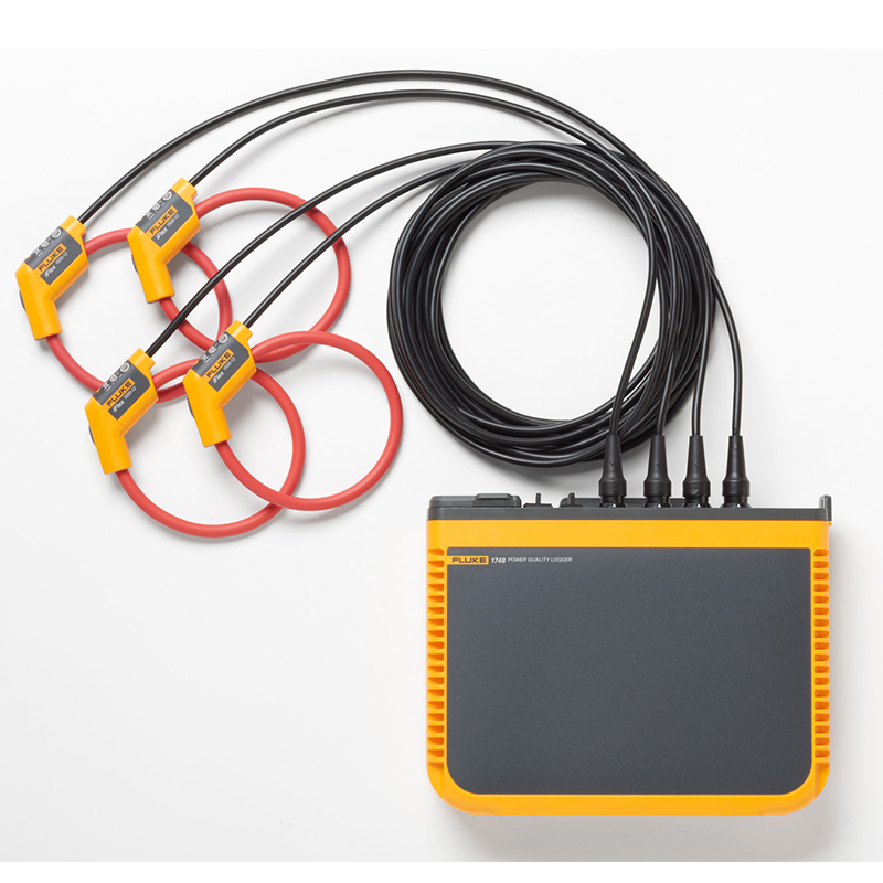
| Flexible Current Probes | No /B version | No /B version | No /B version |
| USB flash drive | - | - | - |
| USB cable | - | - | - |
| 3PHVL-1730 3-Phase and Zero Line Voltage Test Leads | - | - | - |
| Test Lead Set, Red/Black, 0.18 m | - | - | - |
| Test Lead Set, Red/Black, 1.5 m | - | - | - |
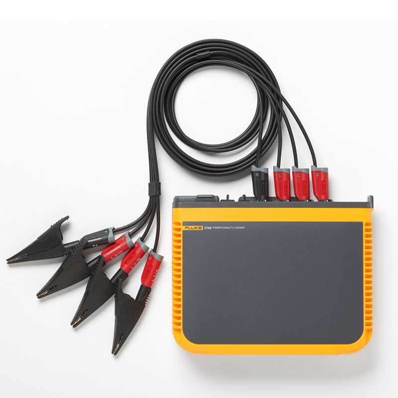
| spring clip | 4 | 4 | 4 |
| 173x/174x Soft Cover | - | - | - |
| Cable Marking Kit | - | - | - |
| MP1-3R/1B-Magnetic Probe, Set of 1 (3 Red, 1 Black) | selectable | 1 | 1 |
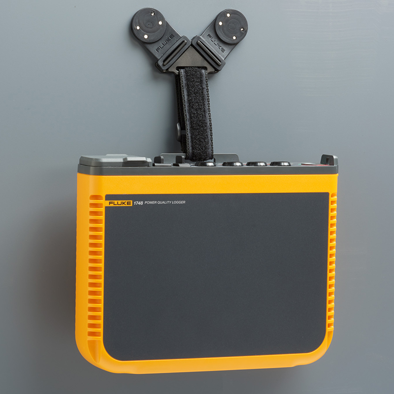
| 174x-Suspension Components | selectable | selectable | - |
11742-6/UPGRADE Option Included
21742-8/UPGRADE or 1746-8/UPGRADE Option Included
Product Specification: Fluke 1742, 1746 and 1748 Online Removable Power Quality Recorders
| Technical indicators | |||||
| accurate | |||||
| parameters | range (of scales or measuring equipment) | Maximum resolution | Intrinsic accuracy at reference conditions (% of reading + % of range) | ||
| input voltage | 1000 V | 0.1 V | ±0.1 of nominal voltage %1, 2 | ||
| Current: direct input | i17xx-flex 1500IP 24 1500 A | 150 A | 0.01 A (min. 1.5 A)3 | ±(1% + 0.02%) | |
| 1500 A | 0.1 A | ||||
| i17xx-flex 3000IP 24 3000 A | 300 A | 0.01 A (3.0 A minimum)3 | ±(1% + 0.03%) | ||
| 3000 A | 0.1 A | ||||
| i17xx-flex 6000IP 36 6000 A | 600 A | 0.01 A (6.0 A minimum)3 | ±(1.5% + 0.03%) | ||
| 6000 A | 0.1 A | ||||
| i40s-EL Current Clamp | 4 A | 1 mA | ±(0.7% + 0.02%) | ||
| 40 A | 10 mA | ||||
| frequency | 42.5 Hz to 69 Hz | 0.01 Hz | ± (0.1%)2 | ||
| auxiliary input | ±10 VDC | 0.1 mV | ±(0.2% + 0.02%) | ||
| Voltage min/max | 1000 V | 0.1 V | ±0.2 of nominal input voltage %1 | ||
| Current min/max | Defined by Annex | Defined by Annex | ±(5% + 0.2%) | ||
| Voltage THD | 1000% | 0.10% | ± 2.5% | ||
| Current THD | 1000% | 0.10% | ± 2.5% | ||
| 2nd to 50th voltage harmonics | 1000 V | 0.1 V | ≥ 1 V: ± 5% of reading | ||
| < 1 V: ±0.05 V | |||||
| 2 to 50th current harmonics | Defined by Annex | Defined by Annex | ≥ 3% of current range: ± 5% of reading | ||
| < 3% of current range: ± 0.15% of range | |||||
| Flicker P LTPST | 0 to 20 | 0.01 | 5% | ||
| Current Probe Accuracy | |||||
| parameters | magnitude of impact | iFlex1500IP-24 | iFlex3000IP-24 | iFlex 6000IP-36 | i40S-EL |
| 150 A / 1500 A | 300 A / 3000 A | 600 A / 6000 A | 4 A / 40 A | ||
| Active power P | PF ≥ 0.99 | 1.2% + 0.005% | 1.2% + 0.0075% | 1.7% + 0.0075% | 1.2% + 0.005% |
| Active electrical energy Ea | |||||
| Apparent power S | 0 ≤ PF ≤ 1 | 1.2% + 0.005% | 1.2% + 0.0075% | 1.7% + 0.0075% | 1.2% + 0.005% |
| Apparent electrical energy Eap | |||||
| Reactive power Q | 0 ≤ PF ≤ 1 | 2.5% of measured apparent power | |||
| Reactive energy Er | |||||
| Power factor PF | - | ±0.025 | |||
| displacement power | |||||
| Factor DPF/cosΦ | |||||
| Other uncertainties (expressed as % of range) | V P-N>250 V | 0.015% | 0.023% | 0.023% | 0.015% |
| 1 In the range of 100 V to 500 V; also known as Udin 2 0 °C - 45 °C range: intrinsic accuracy x 2, 0 °C - 45 °C range: intrinsic accuracy x 3 3 For detailed information, refer to the Operator's Manual Reference Conditions: Ambient: 23 °C ± 5 °C, instrument running for at least 30 minutes, no external electric/magnetic fields, relative humidity <65 % Input conditions: Cosφ/PF=1, sinusoidal signal f=50 Hz/60 Hz, power supply 120 V/230 V ±10 %. Current and power specifications: Input voltage single-phase: 120 V/230 V or three-phase wye/delta: 230 V/400 V Input current: current > 10 % of current range Clamp primary conductor or Rogowski coil in center position Temperature coefficient: 0.1 x specified accuracy per degree Celsius above 28 °C or below 18 °C |
|||||
| Electrical specifications | |||
| power supply | |||
| Voltage range | 100 V to 500 V when supplied via the measuring circuit with a safe input plug | ||
| MA-C8 and 100 V to 240 V (IEC 60320 C7) with standard power cord | |||
| power wastage | 50 VA maximum (15 VA maximum when powered by MA-C8 adapter) | ||
| efficiencies | ≥ 68.2% (energy efficiency code compliant) | ||
| Maximum no-load loss | < 0.3 W (only when using IEC 60320 inputs) | ||
| Mains frequency | 50/60 Hz ± 15% | ||
| batteries | Lithium-ion battery 3.7 V, 9.25 Wh (customer replaceable) | ||
| Battery powered runtime | Usually 4 hours | ||
| charging time | < 6 hours | ||
| data acquisition | |||
| resolution (of a photo) | 16-bit synchronized sampling | ||
| sampling frequency | 10.24 kHz at 50/60 Hz, synchronized to power supply frequency | ||
| Input Signal Frequency | 50/60 Hz (42.5 to 69 Hz) | ||
| Type of wiring method | 1- Φ, 1- Φ IT, Split Phase, 3- Φ Triangle, 3- Φ Y-Shape, 3- Φ Y-Shape IT, 3- Φ Y-Shape Balance, 3- Φ Aron/Blondel (2-element triangles), 3- Φ Triangle Open Arm and Leg, Current Only (Load Study) | ||
| data storage | Internal flash memory (not user replaceable) | ||
| Memory capacity | Typical: 20 logging sessions of 4 weeks, 1-minute intervals, and 500 events | ||
| fundamental interval | |||
| Parameters measured | Voltage, Current, Aux, Frequency, THD V, THD A, Power, Power Factor, Base Wave Power, DPF, Electrical Energy | ||
| Average interval | 1 sec, 5 sec, 10 sec, 30 sec, 1 min, 5 min, 10 min, 15 min, 30 min | ||
| Average time min/max | Voltage, current: full circumferential RMS updated every half-cycle (URMS1/2 in accordance with IEC61000-4-30 Aux, power: 200ms) | ||
| Demand interval (energy meter mode) | |||
| Parameters measured | Electrical energy (Wh, varh, VAh), PF, maximum demand, cost of electrical energy | ||
| intervals | 5 min, 10 min, 15 min, 20 min, 30 min, off | ||
| Power quality measurements | |||
| Parameters measured | Voltage, Frequency, Unbalance, Voltage Harmonics, THD V, Current Harmonics, THD A, TDD, Intervoltage Harmonics, TID V, Intercurrent Harmonics, TID A, Flicker, Power Signal, Upper / Lower Deviation | ||
| Average interval | All parameters 10 minutes 2 hours (long duration flicker PLT) 150/180 cycles (3 s) harmonic (requires software license IEEE519/REPORT) |
||
| subharmonic | 2nd to 50th harmonic Grouping according to IEC 61000-4-7 User-configurable Depending on the application: subgroups (harmonics + interharmonics), subgroups or harmonics-only groups |
||
| interharmonic | 1st to 50th harmonics | ||
| THD | Calculated at 50th voltage harmonic | ||
| event | Voltage: transient drops, surges, interruptions, Current: inrush current 1748: Power signals, transients (low frequency) |
||
| trigger record | RMS plot: full cycle RMS record updated every half voltage and current cycle up to 11 s (URMS1/2 according to IEC 61000-4-30) | ||
| Voltage and current waveform recording up to 200 ms, 10/12 cycles | |||
| Power signal: 10/12 cycles of configured frequency RMS recording up to 120s | |||
| surge current | RMS graph based on 1/2 cycle RMS steady state trigger | ||
| flicker | Conforms to IEC 61000-4-15 and IEEE 1453. | ||
| power line signal | Two user-defined frequencies up to 3 kHz | ||
| PQ status | Summarizes power quality measurements in one table. Provide detailed data for each parameter | ||
| EN 50160 | standards-compliant | ||
| Programmable PQ Limit Values | Conformity of user-defined limit values to local standards | ||
| standards-compliant | |||
| harmonic (wave with frequency an integer multiple of the fundamental) | IEC 61000-4-7: Class 1 | ||
| IEEE 519 (short time harmonics and very short time harmonics) | |||
| power quality | IEC 61000-4-30 Class A, IEC 62586-1, IEC 62586-2 (PQI-A-PI equipment) | ||
| power (output) | IEEE 1459 | ||
| Power quality compliance | EN 50160 | ||
| security level | General: IEC 61010-1: Pollution class 2 | ||
| Measurement: IEC 61010-2-033: CAT IV 600 V / CAT III 1000 V | |||
| Power supply: Overvoltage category IV, pollution class 2 | |||
| Lithium-ion batteries: IEC 62133 | |||
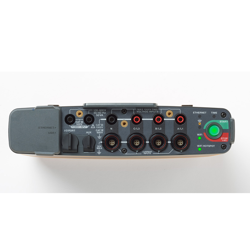
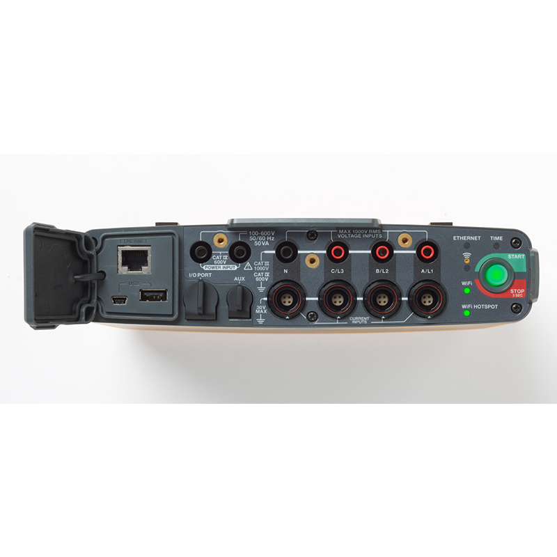
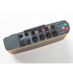
| connector | |||
| USB-A | File transfer via USB flash drive, firmware update, max. supply current: 120 mA | ||
| WiFi | File transfer and remote control via direct connection or WiFi network | ||
| bluetooth | Read auxiliary measurements from Fluke Connect®3000 Series modules (requires supported USB to BLE adapter or WiFi/BLE adapter, check for availability) | ||
| USB-mini | Download data to PC | ||
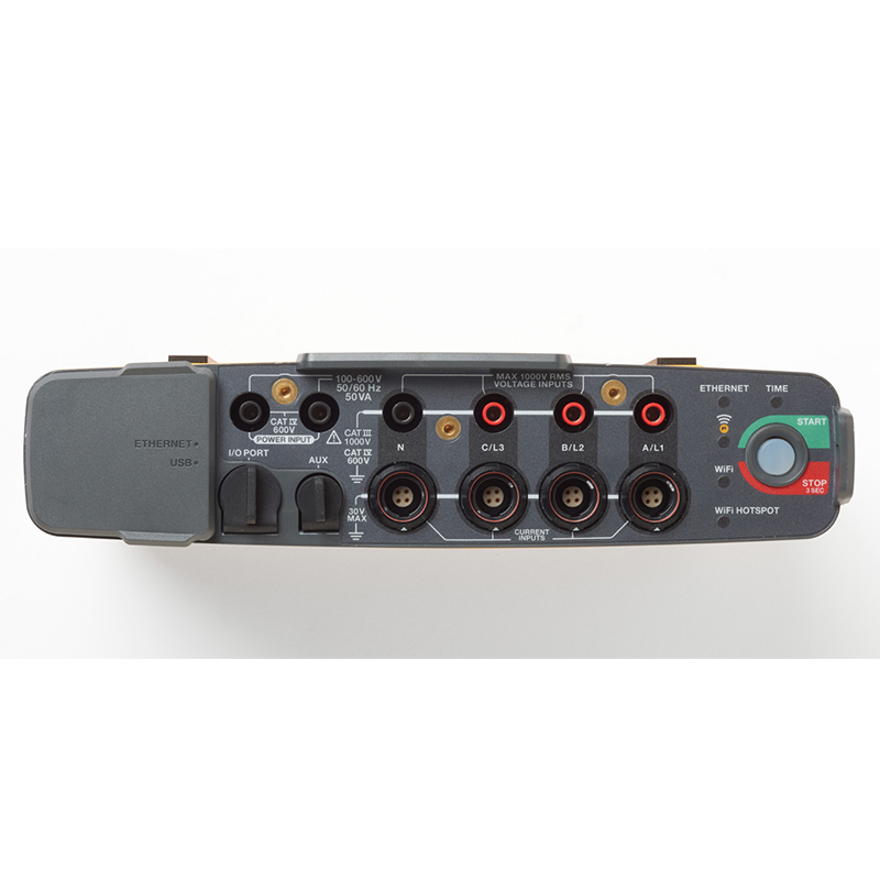
| Voltage Input | |||
| input channel | 4 (three-phase voltage with respect to the zero line) | ||
| Maximum Input Voltage | 1000 Vrms, CF 1.7 | ||
| Input Impedance | 10 MΩ | ||
| bandwidths | 42.5 Hz to 3.5 kHz | ||
| resizing | 1:1, variable | ||
| Voltage safety level | 1000 V CAT III/600 V CAT IV | ||
| Current Input | |||
| input channel | 4 (three-phase and zero line), automatic mode selection for connected sensors | ||
| Input Voltage | Current clamp input: 500 mVrms/50 mVrms; crest factor 2.8 | ||
| Rogowski Roche coil input: 150 mVrms/15 mVrms at 50 Hz, 180 mVrms/18 mVrms at 60 Hz; crest factor 4; all within probe nominal range | |||
| range (of scales or measuring equipment) | 1 A to 150 A/10 A to 1500 A with the i17XX-flex1500 IP 24 Fine Flex Current Probe | ||
| 3 A to 300 A/30 A to 3000 A with the i17XX-flex3000 IP 24 Fine Flex Current Probe | |||
| 6 A to 600 A/60 A to 6000 A with the thin flexible current probe i17XX-flex6000 IP 36 | |||
| 40 mA to 4 A/0.4 A to 40 A (40 A Current Clamp i40s-EL) | |||
| bandwidths | 42.5 Hz - 3.5 kHz | ||
| resizing | 1:1, variable | ||
| auxiliary input | |||
| input channel | 2 (analog and auxiliary adapters, or up to 2 simultaneous BLE devices) | ||
| Input Range | 0 to ± 10 V dc, or 0 to ± 1000 V dc (with optional adapter), 1 reading/second | ||
| proportionality factor | Format: mx + b (gain and offset) user configurable | ||
| Displayed units | User configurable (7 characters, e.g. °C, psi or m/s) | ||
| Wireless Bluetooth connection (check availability) | |||
| input channel | 2 | ||
| Supported Modules | Fluke Connect® 3000 Series | ||
| harvest | 1 reading/second | ||
| Environmental indicators | |||
| operating temperature | -25 °C to +50 °C (-13 °F to 122 °F)1 | ||
| storage temperature | Without battery: -25 °C - +60 °C (-13 °F - 140 °F), with battery: -20 °C - +50 °C (-4 °F - 122 °F) | ||
| Operating humidity | iec 60721-3-3: 3k6: | ||
| -25 °C - +30 °C (-13 °F - +86 °F): ≤ 100 % | |||
| 40 °C (104 °F): 55 % | |||
| 50 °C (122 °F): 35 % | |||
| Working altitude | 2000 m (down to 1000 V CAT II/600 V CAT III/300 V CAT IV up to 4000 m) | ||
| Storage altitude | 12,000 m | ||
| housings | IEC 60529: IP50 | ||
| IEC 60529: IP65, using IP65 rated voltage connectors | |||
| vibration measurement | IEC 60721-3-3 / 3M2 | ||
| Electromagnetic Compatibility (EMC) | EN 61326-1: Industry CISPR 11: Group 1, Class A | ||
| IEC 61000-6-5 Power station environment | |||
| Korea (KCC): Class A equipment (industrial broadcasting and communications equipment) | |||
| USA (FCC): 47 CFR 15 Part B. This product is considered tax-exempt equipment under Section 15.103. | |||
| General technical indicators | |||
| warranty period | Two years (excluding batteries) | ||
| Annex: One year | |||
| Calibration cycle: two years | |||
| sizes | 23.0 cm x 18.0 cm x 5.4 cm (9.1 in x 7.1 in x 2.1 in) | ||
| weights | Instrument: 1 kg (2.2 lb) | ||
| tamper-proof | Connectable safety cable (up to Φ 6mm) | ||
| 1Preheat the product to -10 °C (+14 °F) before turning the unit on. | |||
| i17XX-FLEX1.5KIP Flexible Current Probe Specifications | |||
| measuring range | 1 to 150 A AC / 10 to 1500 A AC | ||
| Probe cable length | 610 mm (24 in) | ||
| Probe Cable Diameter | 7.5 mm (0.3 in) | ||
| weights | 170 g (0.38 lb) | ||
| Minimum bending radius | 38 mm (1.5 in) | ||
| lossless current | 100 kA (50/60 Hz) | ||
| go too far Temperature Coefficient of Operating Temperature Range |
0.05 %/°C of reading (0.028 %/°F of reading) | ||
| operating voltage | 1000 V CAT III, 600 V CAT IV | ||
| Output cable length | 2.0 m (6.5 ft) | ||
| Probe Cable Material | TPR | ||
| weights | 115 g | ||
| Probe Cable Material | TPR | ||
| Connector Material | POM + ABS/PC | ||
| output cable | TPR/PVC | ||
| operating temperature | Tested at a wire temperature of -20 °C to +70 °C (-4 °F to 158 °F), not exceeding 80 °C (176 °F) | ||
| Non-operating temperature | -40 °C to +80 °C (-40 °F to 176 °F) | ||
| Relative humidity in working condition | 15% to 85% Non-Condensing | ||
| protection class | IEC 60529: IP65 | ||
| warranty period | first year | ||


