 Comprehensive test and measurement service provider-Shenzhen Weike Electronic Technology Co.
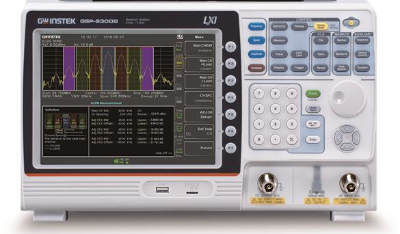


GSP-9300B is a 3GHz spectrum analyzer to meet the general RF measurement needs, it provides 0.025ppm ambient temperature frequency stability and 1ppm/year long-term frequency stability; built-in preamplifier, the lowest noise floor can reach -149dBm/Hz; and more than 20 kinds of measurement applications, such as AM/FM modulated signal analysis, signal channel analysis, CATV parameter testing, and with the TG option can be component frequency response or power linearity testing. There are also more than 20 measurement applications such as AM/FM modulation signal analysis, signal channel analysis, CATV parameter testing, and with the TG option, it can be used to test the frequency response or power linearity of components.
Signal monitoring and processing part, GSP-9300B provides Topographic display mode, the use of color temperature can distinguish between continuous or occasional signals; Spectrogram mode is the spectrum of the display coupled with the display of the time axis, you can observe the frequency of the signal in the time of the change in the situation, and dual-window mode can be used for the two windows for the individual parameter settings; in addition to The Spectrogram mode is a spectrum display with a time axis display for observing the signal frequency and time changes, while the Dual Window mode allows you to set parameters for both windows individually. In addition, it provides user-friendly interfaces, such as status icon display, on-line instructions, multi-language support, and quick storage.
In addition, the GSP-9300B provides convenient settings for production line environments, providing pre-set power-on time, sequence function and limit line measurement...etc. Through the patented thermal conductivity design, it significantly reduces the time needed for warm-up and accelerates the production process; in the choice of equipment, it provides signal tracker, carrying bag, battery module, EMI antenna set and rack In terms of equipment options, we provide signal tracker, battery module, EMI antenna set and rack accessories, no matter it is out of the test or constructed on the automatic test system, the lightweight design can meet a variety of fields.
In summary, the GSP-9300B is a stable, lightweight and suitable test equipment for a variety of applications in the education market, production line environments, general purpose signal monitoring and so on.
Quick Selection
| model number | frequency range | functionality | display mode | scanning time | Standard Interface |
| GSP-9330 | 9KHz-3.25GHz | EMI,P1dB,AM,FM,ASK,FSK,2FSK | Spectrum, Topology, Spectrum | 204us | USB/RS232 |
| GSP-9300B | 9KHz-3GHz | P1dB | Spectrum, Topology, Spectrum | 204us | USB/RS232 |
| GSP-730 | 150KHz-3GHz | 30KHz, 100KHz, 300KHz, 1MHz | spectrogram | 300ms | USB/RS232 |
| GSP-818 | 9KHz-1.8GHz | 10Hz-500KHz in 1-10 steps | spectrogram | 10ms | USB/LAN |
| Detailed specifications | ||
| frequency | ||
| frequency | ||
| realm | 9 kHz to 3 GHz | |
| Setting resolution | 1 Hz | |
| frequency reference source | ||
| accuracy | ±[(final tuning period x aging rate) + stability of temperature + stability of voltage supply | |
| aging rate | ±1 ppm max. | After 1 year of tuning |
| Stability of temperature | ±0.025 ppm | 0 to 50 °C |
| Stability of voltage supply | ±0.02 ppm | |
| Frequency reading stability | ||
| Start, stop, center, mark | ±(frequency display value x accuracy of frequency reference source + 10% x resolution bandwidth + frequency resolution1) | |
| Scanning Points | Maximum 601, minimum 6 | |
| marking counter | ||
| resolution (of a photo) | 1 Hz, 10 Hz, 100 Hz, 1 kHz | |
| accuracy | ± (frequency display value x accuracy of frequency reference source + resolution of frequency counter) | RBW/Span >=0.02 ;Mkr level to DNL>30 dB |
| frequency range | ||
| realm | 0 Hz (zero span), 100 Hz to 3 GHz | |
| resolution (of a photo) | 1 Hz | |
| accuracy | ± frequency resolution | RBW : Automatic |
| phase noise | ||
| Offset from carrier signal | Fc = 1 GHz; RBW = 1 kHz, VBW = 10 Hz; Average ≥ 40 | |
| 10 kHz | <-88 dBc/Hz | typical value |
| 100 kHz | <-95 dBc/Hz | typical value |
| 1 MHz | <-113 dBc/Hz | typical value |
| Analytic Bandwidth Filter | ||
| Filter Bandwidth | 1Hz to 1MHz in 1-3-10 sequence | -3dB bandwidth |
| 200 Hz, 9 kHz, 120 kHz, 1MHz | -6dB bandwidth | |
| accuracy | ± 8%, RBW = 1MHz | indicated value |
| ± 5%, RBW < 1MHz | indicated value | |
| form factor | < 4.5:1 | Typical bandwidth ratio: -60dB:-3dB |
| Video Bandwidth Filters | ||
| Filter Bandwidth | 1 Hz to 1 MHz in 1-3-10 sequence | -3dB bandwidth |
| amplification | ||
| Measurement range | 100 kHz to 1 MHz | From Display Average Noise Level Level (DANL) to +18dBm |
| 1 MHz to 10 MHz | From Display Average Noise Level Level (DANL) to +21dBm | |
| 10 MHz to 3 GHz | From Display Average Noise Level Level (DANL) to +30dBm | |
| attenuator | ||
| Input Attenuator Range | 0 to 50 dB, adjustable in 1 dB steps | Automatic or manual setting |
| Maximum safe input level | ||
| Average continuous power | ≤ +33 dBm | Input attenuator setting ≥ 10 dB |
| dc voltage | ± 50 V | |
| 1dB gain compression | ||
| Total power input to the mixer | > 0 dBm | Typical; fc ≥50 MHz; preamplifier off |
| Total power at the preamplifier end | > -22 dBm | Typical; fc ≥50 MHz; preamplifier on |
| Mixer power level (dBm) = input power (dBm) - input attenuation (dB) | ||
| Display Average Noise Level (DANL) | ||
| Preamp off | RF attenuation 0 dB; RF input connected to a 50 ohm load; RBW 10 Hz; VBW 10 Hz; frequency range 500 Hz ; reference level -60 dBm; track average ≥ 40 times | |
| 9 kHz to 100 kHz | < -93 dBm | indicated value |
| 100 kHz to 1 MHz | < -90 dBm - 3 x (f/100 kHz) dB | |
| 1 MHz to 2.7 GHz | < -122 dBm | |
| 2.7 GHz to 3 GHz | < -116 dBm | |
| Preamp on | RF attenuation 0 dB; RF input connected to a 50 ohm load; RBW 10 Hz; VBW 10 Hz; frequency range 500 Hz ; reference level -60 dBm; track average ≥ 40 times | |
| 100 kHz to 1 MHz | < -108 dBm - 3 x (f/100 kHz) dB | indicated value |
| 1 MHz to 10 MHz | < -142 dBm | |
| 10 MHz to 3 GHz | < -142 dBm + 3 x (f/1 GHz) dB | |
| Bit Level Display Range | ||
| graduated scale | Logarithmic, Linear | |
| unit (of measure) | dBm, dBmV, dBuV, V, W | |
| tagged value | 0.01 dB | logarithmic scale |
| 0.01 % of reference level | linear scale | |
| bitonal display mode | Trajectory, Topographic, Spectrogram | Single/Split Window |
| Number of tracks | 4 | |
| oscillograph | Positive Peak, Negative Peak, Sample, General and RMS (non-video) | Can be set separately for different trajectories |
| track function | Clear/Write; Highest Value/Lowest Hold; View Track; Blanking; Average Arithmetic | |
| Absolute amplitude accuracy | ||
| reference parameter | Center Frequency 160MHz, 10kHz RBW, 1kHz VBW, Spacing 100kHz, Logarithmic Units, 1dB/per frame, Peak Detect Mode, Temperature 20~30 ℃, Signal 0dBm | |
| Turn off the preamplifier | ± 0.3 dB | Reference level 0dBm, attenuation 10dB |
| Turn on the preamplifier | ± 0.4 dB | Reference level -30dBm, attenuation 0dB |
| frequency response | ||
| Turn off the preamplifier | Attenuation 10 dB, reference frequency: 160 MHz, 20 to 30 deg C | |
| 100 kHz to 2.0 GHz | ± 0.5 dB | |
| 2 GHz to 3 GHz | ± 0.7 dB | |
| Turn on the preamplifier | Attenuation 0 dB, reference frequency: 160 MHz, 20 to 30 deg C | |
| 1 MHz to 2 GHz | ± 0.6 dB | |
| 2 GHz to 3 GHz | ± 0.8 dB | |
| Input Attenuation Switching Uncertainty | ||
| Attenuator Setting | 0 to 50 dB, adjustable in 1 dB steps | |
| uncertainties | ± 0.25 dB | Reference Point: 160MHz, 10dB attenuation |
| Analyzing bandwidth filter switching uncertainty | ||
| 1 Hz to 1 MHz | ± 0.25 dB | Reference point: 10kHz RBW |
| Barycentric measurement uncertainty | ||
| Overall amplitude accuracy | ± 1.5 dB | 20 to 30 degrees C, Frequency > 1 MHz, Signal input 0 to -50 dBm, Reference level 0 to -50 dBm, Input attenuation 10 dB, RBW 1kHz, VBW 1kHz, Signal corrected, Preamplifier off |
| ± 0.5 dB | typical value | |
| parasitic noise response | ||
| second-harmonic distortion | Preamplifier off; signal input level: -30 dBm, 0 dB attenuation | |
| +35 dBm | Typical; 10 MHz < fc < 775 MHz | |
| +60 dBm | Typical; 775 MHz ≤ fc < 1.5 GHz | |
| third-order interactive modulation | Preamplifier off; signal input level: -30 dBm, 0 dB attenuation | |
| > 1dBm | 300 MHz to 3 GHz | |
| Bypass noise associated with the input | < -60 dBc | Input signal -30 dBm, attenuation 0 dB, 20 to 30 deg C |
| Residual response (intrinsic) | <-90 dBm | 50 ohm load connected at input; RF attenuation of 0 dB; preamplifier turned off |
| sweep | ||
| sweep time | ||
| realm | 204 us to 1000 s; 50 us to 1000 s | Frequency range > 0 Hz; frequency range equal to 0 Hz, minimum time resolution 10 us |
| sweep mode | Continuous, Single | |
| trigger source | Free Capture; Image Signal; External Signal | |
| Trigger Slope | Positive or negative signal margins | |
| preamplifier | ||
| frequency range | 1 MHz to 3 GHz | |
| gain (electronics) | 18 dB | Marker, built-in on standard machines |
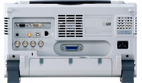
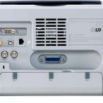
| Front Panel Input/Output | ||
| RF input | ||
| Connector type | N female chassis connector | |
| impedance value | 50 ohms, nominal | |
| VSWR | <1.6 :1 | 300kHz to 3GHz, input attenuation ≥ 10 dB |
| External power supply | ||
| Connector type | SMB Commons | |
| Voltage/current | Maximum +7Vdc, 500mA | Including short-circuit protection |
| USB Master | ||
| Connector type | A-connector | |
| communication protocols | Version 2.0 | Supports full speed/high speed/low speed |
| Micro SD slot | ||
| communication protocols | SD version 1.1 | |
| Supported Cards | MicroSD, MicroSDHC | Up to 32GB available |
| Back Panel Input/Output | ||
| reference output | ||
| Connector type | BNC Female | |
| output frequency | 10 MHz | indicated value |
| Output Amplitude | 3.3V CMOS | |
| Output Impedance | 50 Orme | |
| reference input | ||
| Connector type | BNC Female | |
| Input Reference Frequency | 10 MHz | |
| Input Amplitude | -5 dBm to +10 dBm | |
| Frequency lock range | Within ±5ppm of input reference frequency to | |
| warning output | ||
| Connector type | BNC female chassis connector | Open Collector Control |
| Trigger Input/Gate Scan Input | ||
| Connector type | BNC female chassis connector | |
| Input Amplitude | 3.3V CMOS | |
| switch modes or data streams | automatic switching | |
| LAN (TCP/IP) interface | ||
| Connector type | RJ-45 | |
| (an official) standard | 10Base-T; 100Base-Tx; Auto-MDIX | |
| USB Controlled | ||
| Connector type | B-connector | For remote control only, supports USBTMC |
| communication protocols | Version 2.0 | Supports full/high speed |
| IF output | ||
| Connector type | SMA Female | |
| (electrical) impedance | 50 Aum. | indicated value |
| midrange frequency | 886 MHz | indicated value |
| output collimation | -25 dBm | 10dB attenuation, RF input: 0dBm @1GHz |
| headphone output | ||
| Connector type | 3.5mm stereo jack, wired mono operation | |
| screen output | ||
| Connector type | DVI-I connector (integrates analog and digital), single link, compatible with VGA or HDMI standards using converter | |
| RS-232 interface | ||
| Connector type | D-sub 9-pin female | tx,rx,rts,cts |
| GPIB interface (optional) | ||
| Connector type | IEEE-488 Bus Connectors | |
| AC power input | ||
| power supply (of an appliance etc) | AC 100 V to 240 V, 50 / 60 Hz automatic gear selection | |
| Battery module (optional) | ||
| battery module | 6 cells, rechargeable lithium battery, 3S2P | Conforms to UN38.3 specifications |
| input voltage | DC 11.1V | |
| quantitative (science) | 5200 mAh / 56Wh | |
| General specifications | ||
| Internal data storage capacity | Built-in 16MB | |
| power consumption | <65 W | |
| Warm-up time | < 30 minutes | |
| temperature range | +5 °C to +45 °C | Operating range |
| -20 °C to + 70 °C | Storage range | |
| Size & Weight | 210 x 350 x 100 (mm)8.3 x 13.8 x 3.9 (in)&4.5 kg (9.9 lb) | Overview includes all options (basic + signal tracker + GPIB interface + battery module) |
| Tracking generator (optional) | ||
| Output frequency range | 100 kHz to 3 GHz | |
| Output power level range | -50 dBm to 0 dBm, adjustable in 0.5 dB steps | |
| absolute accuracy | ± 0.5 dB | Reference Point: 160MHz, -10dBm, 10dB attenuation, 20 to 30 degrees C |
| Output flatness | Reference Point 160MHz, -10dBm | |
| 100 kHz to 2 GHz | ± 1.5 dB | |
| 2 GHz to 3 GHz | ± 2 dB | |
| Output level switching inaccuracy | ± 0.8 dB | Referenced to -10 dBm |
| harmonic (wave with frequency an integer multiple of the fundamental) | < -30 dBc | Typical, output collimation -10dBm |
| Reverse Voltage | Maximum +30dBm | |
| Connector type | N female chassis connector | |
| (electrical) impedance | 50 Aum. | indicated value |
| Output VSRW | < 1.6:1 | 300 kHz to 3 GHz, input attenuator: ≥12 dB |
optional
Opt.01 Tracking Source
Opt.02 Battery modules
Opt.03 GPIB interface
Optional Accessories
GSC-009 Portable backpack
GRA-415 Rack Panel
Ordering Information
GSP-9300B 3GHz Spectrum Analysis
attachment (email)
Power cord, easy-to-use manual, factory certificate, CD-ROM
(Includes User's Manual, Program Command Set Manual, SpectrumShot Software, SpectrumShot Easy Manual, and IVI Driver)
")
")

