 Comprehensive test and measurement service provider-Shenzhen Weike Electronic Technology Co.
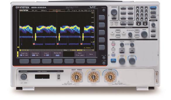


GDS-3000A series oscilloscopes offer record lengths of up to 200Mpts per channel. The advantage of the extra-long record length allows users to maintain a high sampling rate even at low-speed time settings. When the sampling rate is two times higher than the test frequency, it ensures that the captured signals are free of distortion, which facilitates the observation of signal variations for a long period of time at low speeds, which is very helpful for in-depth analysis of signals.
Regarding the waveform update rate, the GDS-3000A reaches up to 200,000 wfm/s, allowing users to easily observe sporadic abnormal signals. The segmented memory, which can continuously capture up to 490,000 segments, can be used in conjunction with trigger condition settings to skip waveforms that have remained unchanged for a long period of time and record only meaningful waveforms, thus providing the most efficient use of memory. A mask function is also provided under the segmented memory, allowing the user to quickly determine if a large number of signals are out of the target range, and to quickly search for the time of the erroneous waveform and the actual signal.
In terms of measurement functions, 38 measurement items are provided. The Fine Scale function allows users to fine-tune the vertical scale as needed to achieve full-size measurements and improve the accuracy of voltage or current measurements. A high-resolution mode acquisition method is provided, effectively eliminating noise and improving the accuracy of automatic measurements. A dynamic vertical scale display is provided on the right side of the on-screen monitor, making it easier for users to interpret the vertical amplitude corresponding to the measured signal.
Standard 1 MΩ and 50Ω input impedance selections allow the user to select the input impedance for impedance matching based on different measurement requirements. The search function allows quick finding of qualified signals based on user settings, which is helpful for finding and comparing sporadic waveforms.
The cursor marking function allows the user to clearly observe the voltage (or current), time and incremental data between the points measured by the cursor. Using the indicator function, the measurement range can be shown by displaying a portion of the waveform.
For frequency domain measurement, GDS-3000A provides FFT measurement function and dual-channel spectrum analyzer. Users can measure and analyze dual-channel frequency domain signals simultaneously. The spectrogram function allows users to easily observe the spectral distribution over time in order to observe the spectral characteristics of the signal.
GDS-3000A provides rich test items for switching power supply testing. Power supply test items provided include AC input analysis items: power quality, Noise, inrush current; DC output analysis required test items: ripple/noise, transient response analysis, on/off analysis, efficiency; control loop response (Bode) and power supply rejection ratio (PSRR); complete switching component analysis items: modulation, switching loss, SOA (Safe Operating Area) and magnetic analysis: B - H curve. The GDS-3000A has built-in power supplies for 50MHz (GCP-530) and 100MHz (GCP-1030) current probes. This feature saves users the cost of purchasing current probe power supplies and reduces the burden of carrying current probe power supplies on the go.
The GDS-3000A comes standard with a dual channel 25MHz arbitrary wave generator. Users can select the arbitrary wave function to store signals measured by analog channels or output them directly from the generator. This function allows users to conveniently generate various types of measurement signals to simulate various signal outputs. It is also equipped with a frequency response analysis function (Bode Plot), which can be applied to product circuit and component characterization verification and analysis, including RLC circuit design, filter design and amplifier design verification and analysis.
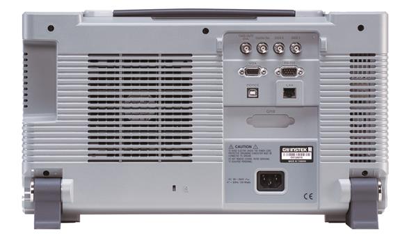
The GDS-3000A provides a wealth of communication interfaces. In addition to the commonly used USB Host, USB device port and LAN port, it includes a highly stable RS232 interface and an optional GPIB interface.
GDS-3000A norm
This specification applies to the GDS-3000A series energized for at least 30 minutes at +20°C to +30°C.
| GDS-3352A | conduit | 2 + Ext |
| bandwidths | DC ~ 350MHz (-3dB) @50Ω/1MΩ input impedance | |
| rising time | 1ns (calculated) | |
| bandwidth limit | 20MHz/100MHz/200MHz* | |
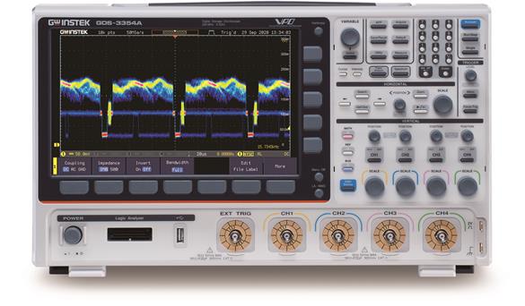
| GDS-3652A | conduit | 2 + Ext |
| bandwidths | DC ~ 650MHz (-3dB) @ 50Ω input impedance
DC ~ 500MHz (-3dB) @1MΩ input impedance |
|
| rising time | 535ps (calculated) | |
| bandwidth limit | 20MHz/100MHz/200MHz/300MHz* | |
| *The bandwidth limit tolerance is ±10%.
|
||
| vertical sensitivity | resolution (of a photo) | 8 bits (Max.12 bits with Hi Res)
For 1MΩ input impedance: 1mV*~10V/div For 50Ω input impedance: 1mV*~1V/div |
| Input coupling | AC, DC, GND | |
| Input Impedance | 1MΩ// 22pF approx. | |
| DC Gain Accuracy | 1mV: ±5% full scale ≥2mV: ±3% full scale |
|
| polarities | Normal & Invert | |
| Maximum Input Voltage | For 1MΩ input impedance: 300Vrms, CAT II
For 50Ω input impedance: 5Vrms max. |
|
| Offset position range | For 1MΩ input impedance.
1mV/div ~ 20mV/div :±1V; 50mV/div ~ 500mV/div: ±10V 1V/div ~ 5V/div : ±100V; 10V/div : ±1000V For 50Ω input impedance. 1mV/div ~ 50mV/div: ±1V; 100mV/div ~ 1V/div : ±10V |
|
| Waveform Signal Processing | +, -, ×, ÷, FFT, User Defined Expression
FFT: Spectral magnitude. Set FFT Vertical Scale to Linear RMS or dBV RMS, and FFT Window to Rectangular, Hamming, Hanning or Blackman. |
|
| trig | Source | CH1, CH2, Line, EXT |
| Trigger Mode | Auto (supports Roll Mode for 100ms/div and slower), Normal, Single | |
| Trigger Type | Edge, Pulse Width(Glitch), Video, Pulse Runt, Rise & Fall(Slope), Timeout, Alternate, Event-Delay(1~65535 events), Time-Delay(Duration, 4ns~10s) , Bus (UART, I2C, SPI, CAN, LIN) | |
| Holdoff range | 4ns to 10s | |
| be coupled (with sth) | AC, DC, LF rej., HF rej., Noise rej. | |
| (level of) sensitivity | 1div | |
| external trigger | Range | ±20V |
| (level of) sensitivity | DC ~ 100MHz Approx. 100mV 100MHz ~ 350MHz Approx. 150mV |
|
| Input Impedance | 1MΩ±3%~22pF | |
| *:Bandwidth limited to 20MHz at 1mV/div and 2mV/div. | ||
| level (of achievement etc) | Time base range | 1ns/div ~ 1000s/div (1-2-5 increments) ROLL: 100ms/div ~ 1000s/div |
| pre-trigger | 10 div maximum | |
| post-trigger | 10,000,000 div maximum. | |
| time base accuracy | ±5 ppm, about ±2ppm increase in error per year | |
| signal acquisition | real time sampling rate | 5GSa/s one channel.
2.5GSa/s dual channels |
| Record length | Max. 200Mpts /CH | |
| Acquisition Mode | Normal, Average, High Resolution, Peak Detect, Single | |
| peak detection | 400ps (typical) | |
| on average | Selectable from 2 to 256 | |
| Number of subparagraphs | 1 to 490,000 maximum | |
| X-Y Mode | X-Axis Input | Channel 1 |
| Y-Axis input | Channel 2 | |
| phase shift | ±3° at 100kHz | |
| Cursor and measurement | cursor (computing) | Amplitude, Time, Gating available.
Unit: Seconds(s), Hz (1/s), Phase (degree), Ratio (%). |
| automatic measurement | 38 sets with indicator: Pk-Pk, Max, Min, Amplitude, High, Low, Mean, Cycle Mean, RMS, Cycle RMS, Area, Cycle Area, ROVShoot, FOVShoot, RPREShoot, FPREShoot, Frequency, Period, RiseTime, FallTime, +Width, -Width, Duty Cycle, +Pulses, -Pulses, +Edges, -Edges FPREShoot, Frequency, Period, RiseTime, FallTime, +Width, -Width, Duty Cycle, +Pulses, -Pulses, +Edges, -Edges, %Flicker, Flicker Idx ,FRR, FRF , FFR, FFF, LRR, LRF, LFR, LFF, Phase. | |
| cursor measurement | Voltage difference between cursors (∆V)
Time difference between cursors(∆T) |
|
| Auto Counter | 6 digits, range from 2Hz minimum to the rated bandwidth | |
| Control Panel Functions | Autoset | Single-button, automatic setup of all channels for vertical, horizontal and trigger systems, with "Undo Autoset", "Fit Screen"/"AC Priority" mode, and "Fine Scale" functions. "Fit Screen"/"AC Priority" mode, and "Fine Scale" functions. |
| Save Settings | 20 sets | |
| Save Waveforms | 20 sets | |
| Save reference waveform | 4 sets | |
Power Measurement
(Optional) |
Power Quality, Harmonics, Ripple, In-rush current, Switching Loss, Modulation, SOA, Transient, Efficiency, B-H curve, Control Loop Response, PSRR. Turn On/Off | |
| AWG | general | |
| conduit | 2 | |
| sampling rate | 200MSa/s | |
| vertical resolution | 14 bits | |
| Maximum frequency | 25 MHz | |
| waveform | Sine, Square, Pulse, Ramp, DC, Noise
Sinc, Gaussian, Lorentz, Exponential Rise, Exponential Fall, Haversine, Cardiac |
|
| Output range | 20 mVpp to 5 Vpp, HighZ.
10 mVpp to 2.5 Vpp, 50Ω |
|
| Output Resolution | 1mV | |
| Output Accuracy | 2% (1 kHz) | |
| offset range | ±2.5 V, HighZ; ±1.25 V, 50 Ω | |
| offset resolution | 1mV | |
| Sine | ||
| frequency range | 100 mHz to 25 MHz | |
| flatness (relative to 1 kHz) |
±0.5 dB < 15MHz.
±1dB 15MHz~25MHz |
|
| harmonic distortion | -40 dBc | |
| Spurious (non-harmonic) | -40 dBc | |
| THD | 1% | |
| S/N Ratio | 40 dB | |
| Square wave/pulse wave | ||
| frequency range | Square: 100 mHz to 15 MHz | |
| Rise/fall time | < 15ns | |
| overshoot | < 3 % | |
| duty cycle | Square: 50%
Pulse: 0.4% to 99.6% |
|
| Minimum pulse width | 30ns | |
| judder | 500 ps | |
| ramp | ||
| frequency range | 100 mHz to 1MHz | |
| linearity | 1% | |
| symmetry | 0 to 100% | |
| spectrum analyzer | frequency range | DC~2.5GHz Max, dual channel with spectrogram (based on Advanced FFT).
Notice: Frequency which exceeds analog front end bandwidth is uncalibrated |
| Span | 1kHz~2.5GHz (Max.) | |
| Resolution bandwidth | 1Hz~2.5MHz (Max.) | |
| reference level | -80dBm to +40dBm in steps of 5dBm | |
| vertical unit | dBV RMS; Linear RMS; dBm | |
| vertical position | -12divs to +12divs | |
| vertical scale | 1dB/div to 20dB/div in a 1-2-5 Sequence | |
| Average noise level displayed | 1V/div ß -40dBm, Avg :16
100mV/div ß -60dBm, Avg :16 10mV/div ß -80dBm, Avg :16 |
|
| spurious response | 2nd harmonic distortion < 35dBc
3rd harmonic distortion < 40dBc |
|
| Frequency domain tracking type | Normal; Max Hold; Min Hold; Average (2 ~ 256) | |
| Detection Methods | Sample; +Peak; -Peak; Average | |
| FFT Window | FFT Factor. Hanning 1.44 Rectangular 0.89 Hamming 1.30 Blackman 1.68 |
|
| Logic analyzer (optional) | sampling rate | 1GSa/s |
| bandwidths | 200MHz | |
| Record length | Per Channel 10M points (max) | |
| input channel | 16 Digital (D15 - D0) | |
| Trigger Type | Edge, Pattern, Pulse Width, Serial bus (I2C, SPI, UART, CAN, LIN), Parallel Bus | |
| Threshold grouping | Settable thresholds for.
d0-d3, d4-d7, d8-11, d12-15 |
|
| Critical value selection | TTL, CMOS(5V,3.3V,2.5V), ECL, PECL,0V ,User Defined | |
| User-defined range of critical values | ±5V | |
| Maximum Input Voltage | ±40 V | |
| Minimum Drive Voltage | ±250 mV | |
| vertical resolution | 1 bit | |
| Frequency Response Analyzer | frequency range | 20Hz to 25MHz |
| Input and output sources | Channel 1 ~ 2 | |
| Number of test points | 10, 15, 30, 45, 90 points per decade selectable for logarithm scale.
2 ~ 1000 points selectable for linear scale |
|
| dynamic range | > 80dB (typical) | |
| Test Amplitude | 10mVpp to 2.5Vpp into 50Ω, 20mVpp to 5Vpp into High-Z, Fixed test amplitude or custom amplitude for each decade. | |
| Test results | Logarithmic or linear overlaid gain and phase plot, may also overlay with reference plots for cross comparison. Test results saved in csv format for Test results saved in csv format for offline analysis. | |
| manual measurement | Tracking gain and phase markers | |
| Drawing scale | Auto-scaled during test | |
| demonstrate | TFT LCD Type | 10.2" TFT LCD WVGA color display |
| Display resolution | 800 horizontal × 480 vertical pixels (WVGA) | |
| Insertion method | Sin(x)/x | |
| waveform display | Dots, vectors, variable persistence (16ms~4s), infinite persistence, gray or color waveforms. | |
| Waveform update rate | 200,000 waveforms per second, maximum | |
| Show Grid Lines | 8 x 10 divisions | |
| display mode | YT, XY | |
| connector | USB Port | USB 2.0 High-speed host port X1, USB High-speed 2.0 device port X1 |
| Ethernet (LAN) | RJ-45 connector X1, 10/100Mbps with HP Auto-MDIX | |
| Go-NoGo BNC | 5V Max/10mA open collector output X1 | |
| Power Supply Receptacles | ±12V / 600mA for current probe use.
Two sets of power supply receptacles for 2CH models. |
|
| RS232C | DB-9 male connector X1 | |
| VGA image output | DB-15 female connector X1, monitor output for display on VGA monitor | |
| Optional GPIB module | Fully programmable with IEEE488-2 compliance | |
| Kensington Security Lock Slot | Rear-panel security slot connects to standard Kensington-style lock. | |
| (sth. or sb) else | Multi-language menu | Available |
| operating environment | Temperature: 0°C to 50°C. Relative Humidity ≤ 80% at 40°C or below. ≤ 45% at 41°C ~ 50°C. |
|
| on-screen help | Available | |
| time function | Time and Date, Provide the Date/Time for saved data | |
| Built-in Flash memory | 800M bytes Single-Level Cell flash memory | |
| Built-in APP | Go/NoGo, DVM, DataLog, Digital Filter, Frequency Response Analyzer, Mask, Mount Remote Disk, Demo | |
| User-defined keys | User can select one of the several different preset functions as shortcut key. | |
| Rated voltage range and power consumption | AC 100V ~ 240V, 50Hz ~ 60Hz, auto selection. power consumption:100W | |
| weights | Approx. 4.6kg | |
| sizes | 420mm(W)X 253mm(H)X 113.8mm(D) | |
Standard Accessories
- User manual CD, Power Cord, Certificate of Calibration
- GTP-351R:350MHz 10:1 passive probe for GDS-3352A (one per channel)
- GTP-501R:500MHz 10:1 passive probe for GDS-3652A (one per channel)
optional
| DS3A-16LA | 16 Channel Logic Analyzer |
| DS3A-GPIB | GPIB Interface (factory install) |
| GTL-248 | GPIB Cable, Double Shielded, 2000mm |
| GTP-033A | 35MHz 1:1 Passive probe |
| GCP-300 | 300 kHz / 200A Current probe |
| GCP-500 | 500 kHz / 150A Current probe |
| GCP-1000 | 1MHz / 70A Current probe |
| GCP-530 | 50MHz / 30A Current probe |
| GCP-1030 | 100MHz /30A Current probe |
| GDP-025 | 25MHz High voltage differential probe |
| GDP-050 | 50MHz High voltage differential probe |
| GDP-100 | 100MHz High voltage differential probe |
| GKT-100 | Deskew fixture |
| GRA-443-E | Rack Mount kit |
| GTL-232 | RS-232C cable, 9-pin female to 9-pin female, Null modem for computer |
Ordering Information
| GDS-3652A |
|
| GDS-3352A |
|


