 Comprehensive test and measurement service provider-Shenzhen Weike Electronic Technology Co.
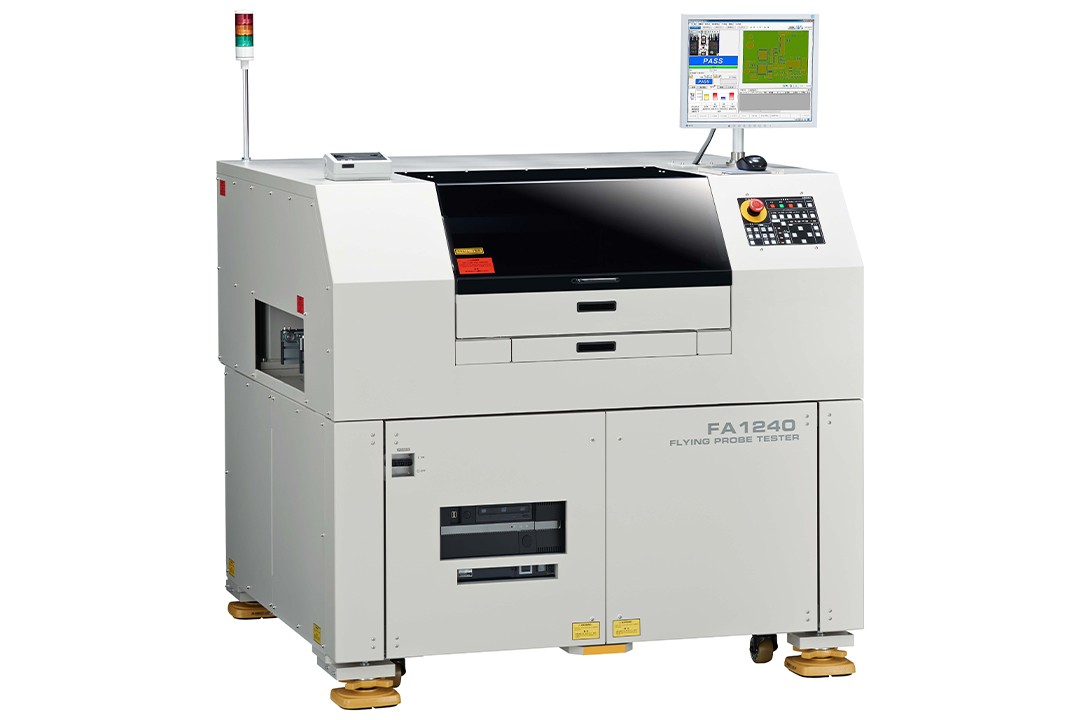


:: A test program that takes full account of component height can be completed in a short period of time by simply following the production process
:: Automatic calculation of arm interference (for use with UA1780)
● Equipped with ultra-wear-resistant probes that can be tested 10 times more often and can be easily replaced without special tools.
:: Detection of suspected contact with electrical components, resulting in increased detection rates in the process.
:: Separation testing and isolation of synthesized components
● Measurement with a voltage of 0.2V or less, which is not damaging to the component.
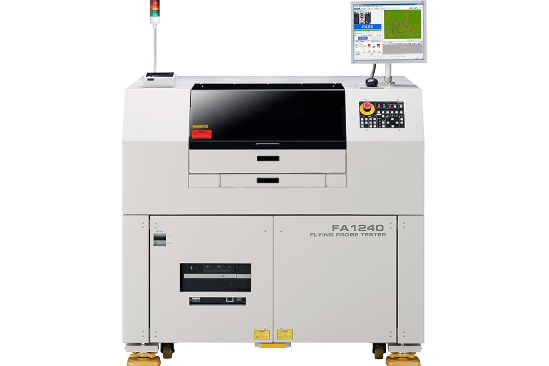
models
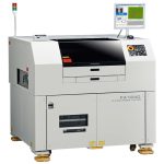
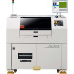
FA1240-61 (for large size substrate)
FA1240-63 (for medium size substrate)
FA1241-61 (for CE large size substrate)
FA1240-63 (for medium size substrate)
FA1241-61 (for CE large size substrate)

Verification of placement accuracy through electrical performance testing
The result of an electrical test must have a measured value.
We visualize invisible electrical characteristics, etc., to confirm compliance with design requirements and guarantee the shipping status with numerical values.
A handheld multimeter (DMM) is always available at the test site for mounted substrates. Flying probe testers not only measure chip values with unknown constants, but also automatically perform "inspection of invisible parts" such as the soldering status between IC pins and the confirmation of complex BGA spots by contacting small-pitch measuring points.
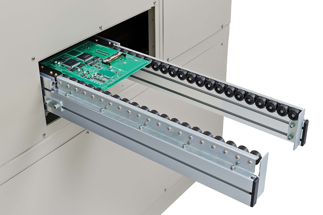
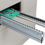
Flying probe testers are used to check whether the substrate is correctly mounted on the production floor, and they are also testing equipment that can realize electrical testing with fewer processes at low cost.

"High-speed, high-precision, non-stationary inspection of battery modules.
The rapid 4-terminal probe enables "high-speed," "high-precision," and "fixation-free" inspection of battery modules.
-

Effective detection of pin gaps and soldering holes
Pin voiding and soldering are the most common defects in the substrate production process that can bypass various tests and reach the market.
Most of the defective pins can be detected by means of real movement test, function test, and existing visual inspection. However, for defective soldering that cannot be recognized from the outside, HIOKI's proprietary resistance test technique can only be used.
The 4-terminal test method (Kelvin method) accurately measures the resistance between the pin and the pad, and accurately identifies the difference in resistance between good and defective soldering. -

Adept at GerberData's point-first philosophy
Simple Program Creation ≠ Simple Production Testing This statement is half right and half wrong. It may have made sense in the days of discrete editing, but now the FA1240 seeks to "simply - and correctly - produce a test program".
The smaller the difference between the program for the test maneuver and the program for the delivery inspection, the shorter the production line downtime (depending on the program debugging time), and the more securely the products can be shipped.
The "rapid" production of "usable" test programs is the result of a joint effort between GerberData and MountData.
Data creation software FIT-LINE UA1780 -

Data creation time 1/10, line stop time 1/15
Used in conjunction with the UA1780 program creation software (option), it reduces rework and allows for high quality test program creation in the shortest possible time.
If you think, "It's so troublesome to create test programs for flying probe testers! If you think so, please try the latest program creation software. -

Adoption of Windows-based workflow diagram guidelines
This is a system that allows you to complete the test program all the way through by simply following the workflow chart. This is a simple system that not only allows you to create data in a simple way, but also allows you to monitor the progress of your followers after they have seen it.
-

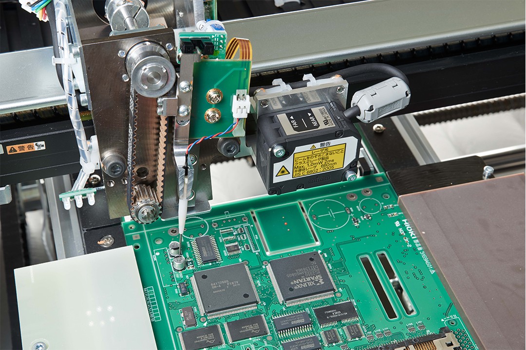
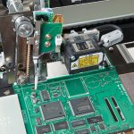
Automatic needle drop test without collision with components
Are you still looking at the tip of the probe and worrying, "Did you touch it? Are you still looking at the tip of the probe and worrying, "Did you hit it, did you not hit it? Are you still checking the tip of the probe while worrying about "Did you touch it?
Operator commissioning time is also significantly reduced if manual probe selection is not required. The height and mounting dimensions of each component are pre-registered in the FA1240 test program. Based on this information, the system automatically selects the test probes (or may select unusable probes). This allows the commissioning of electrical characterization tests to be carried out with peace of mind. -

New ultra-hard probes
The new ultra-hard probes have a wear-free tip even after 3 million tests.
Reduced probe changeover operations and improved test performance for small test points also reduces test time.
Tip wear is the main cause of probe slippage, which not only leads to low Onepass rates, but also causes damage to the test substrate in severe cases. Therefore, probe quality is also an important item in evaluating the performance of test equipment.


Approximate specifications
| FA1240-61 FA1241-61 |
FA1240-63 | |
| Number of arms | 4 arms (L, ML, MR, R) | |
| Test Steps | 40,000 steps (max) | |
| Measurement range | Resistance: 400μΩ ~ 40MΩ Capacitance: 1pF ~ 400mF Inductance: 1μH ~ 100H Diode VZ test: 0~25V Zener Diode VZ Test: 0~25V, 25~80V (Option) Digital Triode: 0~25V Optocoupler: 0 to 25V Short circuit: 0.4Ω~400kΩ Open Circuit: 4Ω ~ 40MΩ DC voltage test: 0~25V Functional voltage test: ±40V (option) Relay ON resistance test: 40m ~ 40Ω (option) FET ON resistance test: 400m ~ 400Ω (option) Simple function test: ±25V (option) |
|
| test speed | 0.025s/step ~ | 0.025s/step ~ |
| positioning accuracy | Within ±100 μm of each arm (X-Y direction) | |
| Movement Repeat Accuracy | Within ±50 μm (test point position) | |
| Minimum test pin spacing | 0.15 mm (4-terminal probe, 0.5 mm) |
0.15 mm (4-terminal probe, 0.5 mm) |
| Test possible sizes | 510W × 460D mm | 400W × 330D mm |
| power supply | AC 200 V (single-phase) 50/60 Hz, 6 kVA (AC230 V for FA1241) |
AC 200 V (single-phase) 50/60 Hz, 5 kVA |
| Dimensions/Weight | 1406W × 1300H × 1380D mm, 1150 kg | 1266W × 1369H × 1425D mm, 1050 kg |


