 Comprehensive test and measurement service provider-Shenzhen Weike Electronic Technology Co.
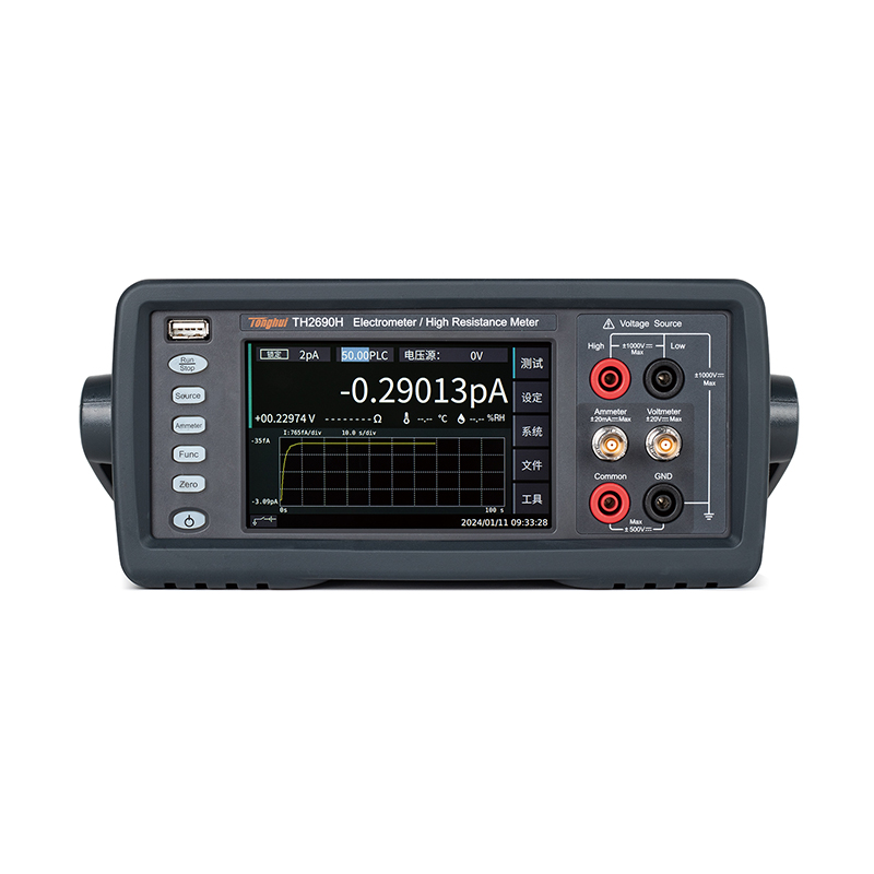
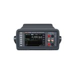
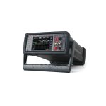
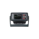


The TH2690 Series of Fly Ampere Meters/Pi Ampere Meters/Electrostatic Meters/High Resistance Meters offer industry-leading measurement capabilities. The Fly Ampere Meter/Electrostatic Meter has a 0.01fA (10-17A) minimum current resolution to meet the needs of weak current measurement in most scenarios. The high resistance meter's built-in 1000V voltage source supports measurements up to 1000PΩ (1018Ω) resistance.
For different test objects and test environments, Tonghui also provides a variety of adapted accessories.
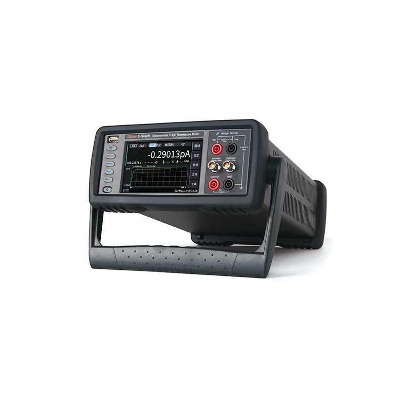
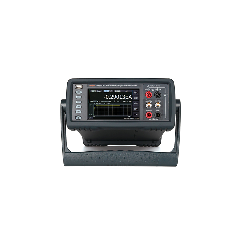
Unlike traditional Picoammeters and High Resistance Meters, the TH2690 Series features a 5" color LCD capacitive touch screen for intuitive and convenient operation. The TH2690 series also offers a variety of view modes for users to observe the data. In addition to digital format, measurement data can be converted to histogram and trend graph format, allowing users to instantly view the distribution pattern or trend of measurement data.
The TH2690 series offers six models, giving users the flexibility to purchase the right instrument for their actual testing needs.
| Quick Selection | TH2690 | TH2690A | TH2690H | TH2691 | TH2691A | TH2691H |
| Measurement Resolution | 6½ bits | |||||
| Current Resolution | 0.1fA | 0.01pA | 0.01fA | 0.1fA | 0.01pA | 0.01fA |
| Maximum resistance | 100PΩ | 1PΩ | 1000PΩ | - | - | - |
| Charge Measurement | 1fC-2μC | - | 1fC-2μC | - | - | - |
| Temperature and humidity measurement | √ | - | √ | - | - | - |
| voltage source | ±1000V | - | - | - | ||
| Voltage Resolution | 1μV | - | - | - | ||
Functional Features
1.0.01fACurrent Measurement Resolution
When studying material properties or determining device performance, it is often necessary to measure extreme currents and resistances such as fA/PΩ, which cannot be achieved by traditional digital multimeters (DMMs). The TH2690 series of femtometers/electrostatic meters provide industry-leading 0.01fA current measurement resolution and 1000PΩ resistance measurement, which is a perfect realization of material measurements and can meet the measurement needs of the present and the future.

2. 10,000 readings/second data readout rate
Measurement speed is generally determined by the integration period in the integration setup, which is usually an integer multiple of the period at labor frequency (PLC). The shorter the integration period, the better, provided that sufficient averaging times are provided to avoid the influence of industrial noise on the measurement.
While conventional instruments are unable to capture fast transients due to their relatively slow read rates, the TH2690 Series reads data at rates up to 10,000 readings per second, capturing a finer-grained response of the device under test.
3. The statistical chart shows
The TH2690 series can display test results graphically in real time on the main interface to show the dynamic characteristics of the device under test (DUT). There are two types of graphs: curve graphs and histograms.
The following picture shows the setting interface

1) Curve chart (time base view) display
The TH2690 can conveniently plot a variety of graphs, including I-t, V-t, R-t, Q-t, and I-R (specific graphical display capabilities depend on the model used). This powerful and comprehensive graphical display capability makes it easier to obtain valuable data when making sensitive measurements.
2) Histogram display
A certain amount of noise fluctuation is present in any measurement environment, so low-level measurement data carry a certain amount of statistical uncertainty. The traditional way of dealing with this is to evaluate the measurement data by plotting a histogram at the end of the measurement (usually on a PC). However, this process can become lengthy if you need to perform multiple measurements and test setup debug cycles.
The TH2690 series features a real-time, auto-scaling histogram display that allows you to adjust measurement settings in a timely manner without having to process data after measurement. The histogram is displayed below the measurement data, making it easy to compare the cumulative data on the histogram with the real-time measurement data.

4. Scanning Output
The TH2690 can be set to output single step wave, double step wave, square wave, and custom list outputs. Click on the Settings - Source Settings tab to make the settings. The setting interface is as follows:

5. Sorting function
The TH2690 can be used to determine and sort test results. There are two modes for grading and sorting, and up to 7 judgment conditions can be set. The setting interface is shown on the right:
Among them, the Grading mode is to execute the limit judgment until it encounters a failure to jump out, output the current failure bit, otherwise continue to the next limit judgment, and if all pass, output the last pass bit.
Sorting (Sorting) mode is to perform limit determination until it encounters a qualified jump out, output the current qualified bit, otherwise continue to the next limit determination, if all fail, output the last failed bit.

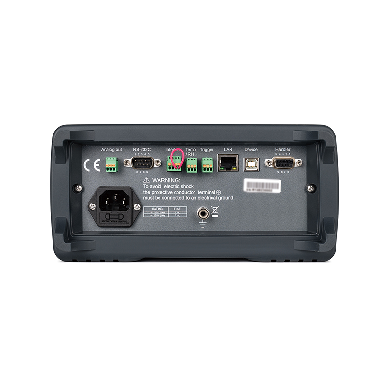
6. HANDLER interface definition
1,2,3 are signal input pins, corresponding to IN1, IN2, IN3 in the above figure. you can change the signal definition.
4,5,6,7 are signal output pins, corresponding to OUT4, OUT5, OUT6, OUT7 in the above figure. can change the signal output mode.
7. Error messages
When the instrument is operated wrongly or the instrument self-tests wrongly, etc., the error will be reported in the information column below the instrument, click on the Tools-Error Message icon, where you can view the alarm information, and you can eliminate the error according to the prompts.

8. Specialized temperature and humidity probe provides more reliable temperature and humidity data
Temperature and humidity are critical parameters in high value resistance measurements.The TH2690, TH2690H high resistance meters provide a temperature and humidity sensor interface and are equipped with a dedicated temperature and humidity probe. Digital temperature and humidity probes can be used to determine temperature and humidity, providing more accurate temperature data than thermocouples.
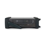
9. A variety of accessories to cope with different test environments and test pieces
The TH2690 is equipped with a variety of optional accessories to adapt to different DUTs and further enhance its test results. The main ones include resistivity test box and component test fixture.
Resistivity test kits are equipped with a variety of electrode sizes that can be used to measure the surface resistivity and body resistivity of materials of different specifications.
Component test fixtures are equipped with a variety of test modules to cope with the measurement of SMD devices, axial leaded devices and other packages.

- Resistivity measurement (option)
The TH2690 series is available with the optional TH26090 for resistivity measurements.
a) Program Configuration:
| serial number | model number | name (of a thing) | mandatory option | note |
| 1 | TH2690 | Flying Ampere Meter/Electrostatic Meter/High Resistance Meter Main Unit | R | |
| 2 | TH26090 | Resistivity test kit | R | option |
| 3 | note | TH2690 firmware upgrade to the latest |
b) TH26090 resistivity test kit
| functionality | instructions |
| test voltage | 0-±1000V |
| Test Electrodes | Φ26mm, Φ38mm, Φ50mm (standard), 3 options available |
| Test Current | 0-10mA |
| contact pressure | ≤10kg |
| measured parameter | Surface resistance Rs, surface resistivity ρs, body resistance Rv, body resistivity ρv |
c) Volume resistance Rv, volume resistivity ρv measurement
A voltage source Vs was applied to the upper electrode, a large current of Im was specified to flow through the test sample, and the volume resistance Rv was subsequently calculated using the formula Rv=Vs/Im.
Large currents flowing from the test sample to the protection electrode and surface currents flowing from the upper electrode to the protection electrode are leakage currents; however, these currents go to the low side of Vs and do not affect the magnitude of the ammeter current (Im) used to calculate Rv.
The volume resistivity ρv can be calculated using the formula ρv = EAR/STHxRv, where.
EAR = Effective area
STH = Sample thickness Sample thickness.
a) Measurement of surface resistance Rs, surface resistivity ρs
A voltage source Vs is applied to the ring guard electrode and a current flows on the surface of the test sample from the guard electrode to the main electrode, the surface current being designated as Im. The surface resistance Rs can be calculated by the formula Rs = Vs/Im.
The current flowing from the guard ring to the upper electrode is a leakage current; however, this current will flow into the low side of Vs and will have no effect on the magnitude of the ammeter current (Im) used to calculate Rv.
The surface resistance can be calculated from the equation ρs = EPER/GLENxRs, where.
EPER = Effective perimeter effective perimeter
GLEN = Gap length Interval length
| Product Model | TH2690 | TH2690A | TH2690H | TH2691 | TH2691A | TH2691H | |||||||
| demonstrate | |||||||||||||
| monitor (computer) | 5.0" Capacitive Touch Color LCD Monitor | ||||||||||||
| Measurement resolution | 6½ bits | ||||||||||||
| Current Measurement | |||||||||||||
| range (of scales or measuring equipment) | accurate | resolution (of a photo) | accurate | resolution (of a photo) | accurate | resolution (of a photo) | accurate | resolution (of a photo) | accurate | resolution (of a photo) | accurate | resolution (of a photo) | |
| 2pA | ------ | ------ | ------ | ------ | ± (1%+5fA) | 0.01fA | ------ | ------ | ------ | ------ | ± (1%+5fA) | 0.01fA | |
| 20pA | ± (1%+5fA) | 0.1fA | ------ | ------ | ± (1%+5fA) | 0.1fA | ± (1%+5fA) | 0.1fA | ------ | ------ | ± (1%+5fA) | 0.1fA | |
| 200pA | ±(0.5%+5fA) | 0.1fA | ------ | ------ | ±(0.5%+5fA) | 0.1fA | ±(0.5%+5fA) | 0.1fA | ------ | ------ | ±(0.5%+5fA) | 0.1fA | |
| 2nA | ±(0.2%+50fA) | 1fA | ±(0.2%+50fA) | 1fA | ±(0.2%+50fA) | 1fA | ±(0.2%+50fA) | 1fA | ±(0.2%+50fA) | 1fA | ±(0.2%+50fA) | 1fA | |
| 20nA | ±(0.2%+3pA) | 10fA | ±(0.2%+3pA) | 10fA | ±(0.2%+3pA) | 10fA | ±(0.2%+3pA) | 10fA | ±(0.2%+3pA) | 10fA | ±(0.2%+3pA) | 10fA | |
| 200nA | ±(0.2%+5pA) | 100fA | ±(0.2%+5pA) | 100fA | ±(0.2%+5pA) | 100fA | ±(0.2%+5pA) | 100fA | ±(0.2%+5pA) | 100fA | ±(0.2%+5pA) | 100fA | |
| 2μA | ±(0.1%+50pA) | 1pA | ±(0.1%+50pA) | 1pA | ±(0.1%+50pA) | 1pA | ±(0.1%+50pA) | 1pA | ±(0.1%+50pA) | 1pA | ±(0.1%+50pA) | 1pA | |
| 20μA | ±(0.05%+500pA) | 10pA | ±(0.05%+500pA) | 10pA | ±(0.05%+500pA) | 10pA | ±(0.05%+500pA) | 10pA | ±(0.05%+500pA) | 10pA | ±(0.05%+500pA) | 10pA | |
| 200μA | ±(0.05%+5nA) | 100pA | ±(0.05%+5nA) | 100pA | ±(0.05%+5nA) | 100pA | ±(0.05%+5nA) | 100pA | ±(0.05%+5nA) | 100pA | ±(0.05%+5nA) | 100pA | |
| 2mA | ±(0.05%+50nA) | 1nA | ±(0.05%+50nA) | 1nA | ±(0.05%+50nA) | 1nA | ±(0.05%+50nA) | 1nA | ±(0.05%+50nA) | 1nA | ±(0.05%+50nA) | 1nA | |
| 20mA | ±(0.05%+500nA) | 10nA | ±(0.05%+500nA) | 10nA | ±(0.05%+500nA) | 10nA | ±(0.05%+500nA) | 10nA | ±(0.05%+500nA) | 10nA | ±(0.05%+500nA) | 10nA | |
| Resistance Measurement | |||||||||||||
| range (of scales or measuring equipment) | accurate | resolution (of a photo) | accurate | resolution (of a photo) | accurate | resolution (of a photo) | ------ | ||||||
| 1MΩ | ±(0.135%+1Ω) | 1Ω | ±(0.135%+1Ω) | 1Ω | ±(0.135%+1Ω) | 1Ω | ------ | ||||||
| 10MΩ | ±(0.135%+10Ω) | 10Ω | ±(0.135%+10Ω) | 10Ω | ±(0.135%+10Ω) | 10Ω | ------ | ||||||
| 100MΩ | ±(0.185%+100Ω) | 100Ω | ±(0.185%+100Ω) | 100Ω | ±(0.185%+100Ω) | 100Ω | ------ | ||||||
| 1GΩ | ±(0.285%+1kΩ) | 1kΩ | ±(0.285%+1kΩ) | 1kΩ | ±(0.285%+1kΩ) | 1kΩ | ------ | ||||||
| 10GΩ | ±(0.41%+10kΩ) | 10kΩ | ±(0.41%+10kΩ) | 10kΩ | ±(0.41%+10kΩ) | 10kΩ | ------ | ||||||
| 100GΩ | ±(0.41%+100kΩ) | 100kΩ | ±(0.41%+100kΩ) | 100kΩ | ±(0.41%+100kΩ) | 100kΩ | ------ | ||||||
| 1TΩ | ±(0.45%+1MΩ) | 1MΩ | ±(0.45%+1MΩ) | 1MΩ | ±(0.45%+1MΩ) | 1MΩ | ------ | ||||||
| 10TΩ | ±(0.75%+10MΩ) | 10MΩ | ------ | ------ | ±(0.75%+10MΩ) | 10MΩ | ------ | ||||||
| 100TΩ | ±(2.6%+100MΩ) | 100MΩ | ------ | ------ | ±(0.75%+100MΩ) | 100MΩ | ------ | ||||||
| 1PΩ | ------ | ------ | ------ | ------ | (2.6%+1GΩ) | 1GΩ | ------ | ||||||
| range (of scales or measuring equipment) | Current range | voltage source | Current range | voltage source | Current range | voltage source | ------ | ||||||
| 1MΩ | 200μA | 20V | 200μA | 20V | 200μA | 20V | ------ | ||||||
| 10MΩ | 20μA | 20V | 20μA | 20V | 20μA | 20V | ------ | ||||||
| 100MΩ | 2μA | 20V | 2μA | 20V | 2μA | 20V | ------ | ||||||
| 1GΩ | 200nA | 20V | 200nA | 20V | 200nA | 20V | ------ | ||||||
| 10GΩ | 20nA | 20V | 20nA | 20V | 20nA | 20V | ------ | ||||||
| 100GΩ | 2nA | 20V | 2nA | 20V | 2nA | 20V | ------ | ||||||
| 1TΩ | 2nA | 200V | 2nA | 200V | 2nA | 200V | ------ | ||||||
| 10TΩ | 200pA | 200V | ------ | ------ | 200pA | 200V | ------ | ||||||
| 100TΩ | 20pA | 200V | ------ | ------ | 20pA | 200V | ------ | ||||||
| Maximum Measuring Resistance | 100PΩ | 1000TΩ | 1000PΩ | ------ | |||||||||
| Voltage measurement (separate input unit) | |||||||||||||
| range (of scales or measuring equipment) | accurate | resolution (of a photo) | ------ | ||||||||||
| 2V | ±(0.05%+40μV) | 1μV | ------ | ||||||||||
| 20V | ±(0.05%+400μV) | 10μV | ------ | ||||||||||
| Input Impedance | >200TΩ | ------ | |||||||||||
| Charge measurement (indicator valid for 1s) | |||||||||||||
| range (of scales or measuring equipment) | accurate | resolution (of a photo) | ------ | accurate | resolution (of a photo) | ------ | |||||||
| 2nC | ±(0.5%+50fC) | 1fC | ------ | ±(0.5%+50fC) | 1fC | ------ | |||||||
| 20nC | ±(0.5%+500fC) | 10fC | ------ | ±(0.5%+500fC) | 10fC | ------ | |||||||
| 200nC | ±(0.5%+5pC) | 100fC | ------ | ±(0.5%+5pC) | 100fC | ------ | |||||||
| 2μC | ±(0.5%+50pC) | 1pC | ------ | ±(0.5%+50pC) | 1pC | ------ | |||||||
| voltage source | |||||||||||||
| range (of scales or measuring equipment) | accurate | resolution (of a photo) | ------ | ||||||||||
| 20V | ±(0.05%+2mV) | 1mV | ------ | ||||||||||
| 1000V | ±(0.05%+100mV) | 35mV | ------ | ||||||||||
| range (of scales or measuring equipment) | Maximum Output Current | ------ | |||||||||||
| 20V | ±20mA | ------ | |||||||||||
| 1000V | ±1mA | ------ | |||||||||||
| Voltage Source Function | DC, Sweep (Single Sweep, Dual Sweep, List Sweep), ARB (Square Wave) | ------ | |||||||||||
| Temperature measurement range and accuracy | |||||||||||||
| -40°C-10°C | 1°C | ------ | |||||||||||
| 10°C-55°C | 0.5°C | ------ | |||||||||||
| 55°C-80°C | 1°C | ------ | |||||||||||
| Humidity measurement range and accuracy | |||||||||||||
| 0-20%RH | 4% | ------ | |||||||||||
| 20-80%RH | 3% | ------ | |||||||||||
| 80-100%RH | 4% | ------ | |||||||||||
| view mode | Gauge View, Graph View, Histogram, Scroll View | ||||||||||||
| test terminal | |||||||||||||
| Voltage Input | Triaxial BNC | ------ | |||||||||||
| Current Input | Triaxial BNC | ||||||||||||
| voltage output | √ | ------ | |||||||||||
| COMMON | √ | ||||||||||||
| GROUND | Banana (constellation) | ||||||||||||
| connector | |||||||||||||
| D/A output | ±2VFS | ||||||||||||
| HANDLER | √ | ||||||||||||
| communication interface | RS232, USB DEVICE, USB HOST, LAN, GPIB | ||||||||||||
| Sensor Input | temperature and humidity | ------ | |||||||||||
| Interlocking Inputs | √ | ------ | |||||||||||
| Ambient temperature and humidity | |||||||||||||
| Operating temperature and humidity range | 0°C - 45°C, 30% - 80%, non-condensing | ||||||||||||
| Storage temperature and humidity range | -20°C to 60°C, 10% to 90%, non-condensing | ||||||||||||
| Precision guaranteed temperature and humidity | 23°C±5°C, 30%-80%RH | ||||||||||||
| preheating time | 1 hour | ||||||||||||
| Change in ambient temperature | Less than ±3°C after self-calibration | ||||||||||||
| calibration period | 1 year | ||||||||||||
| General indicators | |||||||||||||
| power supply | AC: 90V-264V,50/60Hz; or DC: 127V-370V | ||||||||||||
| power (output) | 60W | ||||||||||||
| Shelf Size | 215(W)×88(H)×412(D) | ||||||||||||
| Overall dimensions | 235(W)×111(H)×440(D) | ||||||||||||
| weights | 3.5kg | ||||||||||||
■ 6½ bit measurement resolution
■ 5.0-inch capacitive touch screen
■ Current resolution up to 0.01fA (10-17A)
■ Measuring resistance up to 1000PΩ (1018Ω)
■ Built-in voltage source: ±1000V, resolution: 1mV
■ Supports voltage measurement up to 20V
■ Charge measurement down to 2nC range
■ Temperature and humidity measurements
■ Four measurement modes: high resistance meter, voltmeter, ammeter, electrostatic meter
■ Independent current and voltage measurements
■ Input impedance >200TΩ
■ Current range: 2pA-20mA, current resolution up to 0.01fA (10)-17A)
■ Internal resistance voltage drop in the lowest current range <20μV
■ Time-domain view to capture transient signal effects and select specified measurements
■ Support for data logging
■ Configuration of a special shielding test box
- Material characterization testing semiconductors, nanomaterials, polymer materials, dielectric materials, electrochemical materials, ferroelectric materials, graphene, ceramics, biomaterials, rubber, thin films, metals, organic materials, etc.
- Leakage current and insulation resistance testing of electronic components Capacitors, resistors, diodes, transistors, sensors, TFTs and CNTs and other types, optoelectronic devices, nano devices, solar cells, switches, relays, etc.
- Electronic/non-electronic system ion beam, electron beam, sensing system, particle measurement, embedded precision instruments, etc.
- I-V Characterization of Semiconductors and Other Devices
- Body Resistance/Surface Resistivity Measurement
| standard equipment | |||||
| Accessory Name | model number | ||||
| short circuit block | TH26058C | ||||
| High Voltage Test Lines | TH90003D | ||||
| High Voltage Test Lead (Red) | TH90003E | ||||
| Temperature and humidity sensors | TH2690_THS | ||||
| Tri-Coaxial Connection Cable | TH26058D | ||||
| Φ4 Alligator Clip | TH26058F | ||||
| Φ4 anti-electricity lantern plug cable | TH26058G | ||||
| USB interface cable | TH26017(USB Connection Cable 2H/USB-AM USB-BM/L 1500) | ||||
| optional | |||||
| Accessory Name | model number | ||||
| Tri-Coaxial Connection Cable | TH26058B | ||||
| Φ4 Lantern Pen | TH26058E | ||||
Recommended


