 Comprehensive test and measurement service provider-Shenzhen Weike Electronic Technology Co.
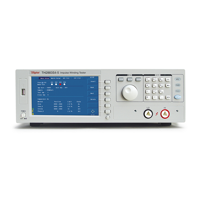


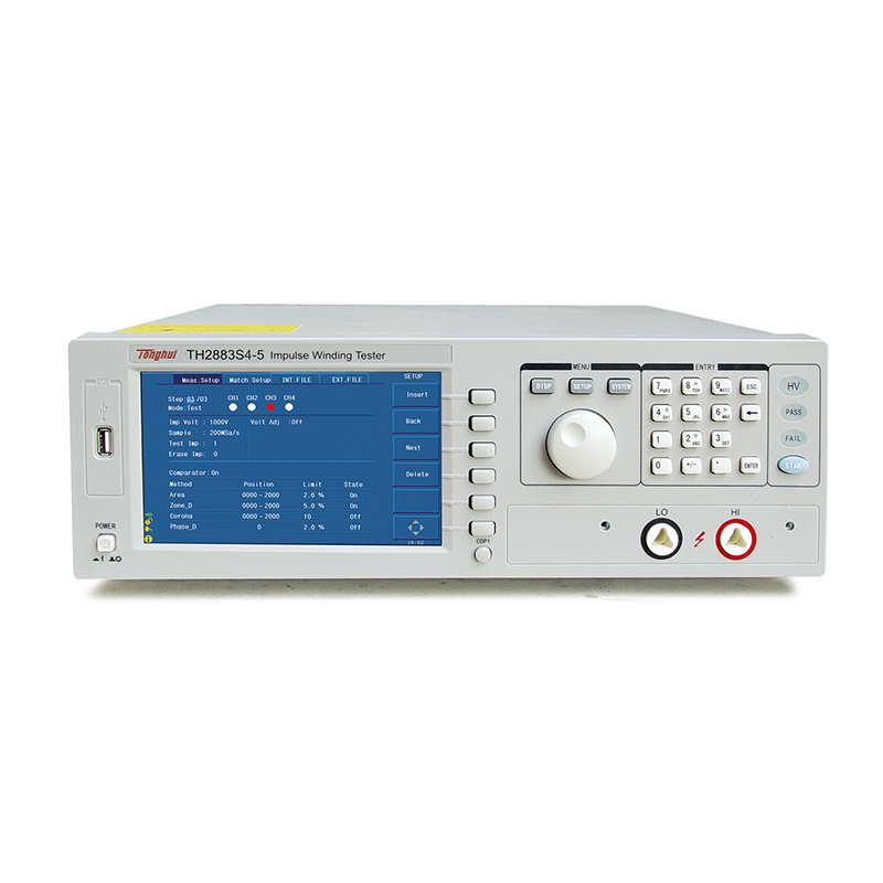

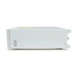


The TH2883 series is a line of pulsed coil testers developed by Tonghui. It provides a complete range of coil tester solutions from low voltage 30V to high voltage 10kV, single channel to multi-channel (maximum 8 channels).
The product line adopts the current mainstream 32bit CPU and high-density SMD mounting process, 65k color 7-inch widescreen TFT display. The operating functions are simple and easy to use, and the display interface is fresh and bright. Minimum 30V, maximum 10kV covers a wide range of pulse voltage, as low as 1uH inductance coil test, up to 200Msps sampling rate, 6k Bytes of storage depth, so that your test "everything".
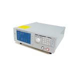
TH2883 series is divided into TH2883-1, TH2883-5 and TH2883-10 according to different output voltages. TH2883-1 is a low inductance pulse coil tester with minimum 30V and maximum 1200V pulse voltage, which can test coils with inductance as low as 1uH, and it is the ideal test product for inductance coils used in switching power supplies, etc. TH2883-5 has a wide range of pulse voltage from 100V to 5000V, which is the standard product for testing all kinds of coils. The TH2883-5 has a wide range of pulse voltages from 100V to 5000V, making it ideal for testing a wide variety of coils, and the TH2883-10 has a pulse output voltage of up to 10kV, allowing for turn-to-turn testing of higher insulation voltages. The three single-channel testers can be expanded to 10 channels with the TH28831 turn-to-turn insulation multi-scanner.
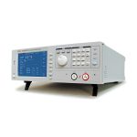
The TH2883 series also provides two all-in-one units for 4-channel and 8-channel multiplexed testing, and their corresponding models are the TH2883S4-5 and TH2883S8-5 for users to choose flexibly.
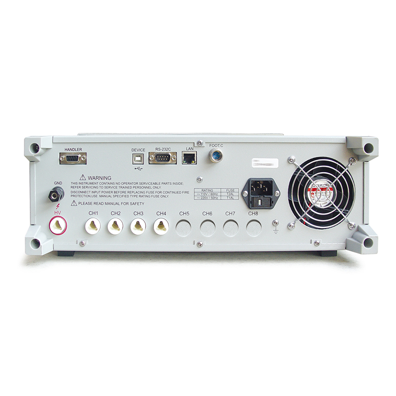
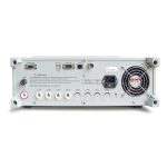
The TH2883 series products come standard with USBHost, RS232C, USB Device and LAN interfaces, which are convenient for both quick saving of your graphs and remote control.

Functional Features
A. Coil Performance Analysis
Coil products (such as transformers, motors, etc.) due to the winding materials, magnetic materials, skeleton, processing technology and other factors will produce a coil between layers, turns and pins and other insulation performance degradation. TH2883 series of pulsed coil testers by comparing the attenuation of the coil under test oscillator waveforms with the standard waveforms to determine the inductance of the windings, the quality factor (Q), the number of windings of the turn difference between the turn interlayer short circuit can also determine the material difference. Short circuit, in the case of magnetically conductive materials can also determine the difference in material, the occurrence of corona discharge under high-voltage pulse can also be on the winding layer or multiple winding insulation between the bad to determine.

The self-excited oscillation decay waveform in Figure A-1 is directly related to the inductance value of the coil, L, and the quality factor, Q, which are inextricably linked to the number of turns of the coil, the manufacturing process, and whether or not the coil is hollow, as well as to the properties of the permeable material. Since the applied voltage is a high-voltage pulse voltage, short-circuits in the coil, partial short-circuits between turns, or corona discharges between layers or turns due to insulation damage are naturally easy to detect.

B. Four Waveform Judgment Methods
a) Methods of area comparison
As shown in Fig. B-1, the area of the test waveform of the coil under test is calculated (integrated) in an arbitrarily specified interval A to B and compared with the area of the standard waveform in this interval, and the percentage of the difference between the area of the two waveforms and the area of the standard waveform in the interval is used as the basis for judgment, and the basis for judgment is set in percentage.

The waveform area is approximately proportional to the energy loss, so the area comparison method can be used to determine the energy loss in the coil and effectively detect coil-to-layer and turn-to-turn shorts.
b) Methods of comparison of area differences
As shown in Fig. B-2, the difference between the Y-axis direction of the test waveform of the coil under test and the standard waveform is calculated in an arbitrarily specified interval A to B (the result of the integration calculation is the shaded portion of the interval A to B), and the area of the standard waveform is compared in this interval, and the reference is set in terms of a percentage.

The area difference comparison method mainly shows the difference in inductance L and the energy loss. This comparison method can effectively detect the difference in inductance L between the standard coil and the coil under test.
c) Corona comparison methods
As shown in Fig. B-3, independent of the difference of waveforms, only the high-frequency components are detected in the corona discharge spikes contained in the test waveform of the coil under test in the arbitrarily specified interval A to B for non-destructive extraction, and the calculated results are compared with the set value, which is an integer, to judge whether the corona discharge quantity is qualified or not.

This method has the most obvious response to the coil's internal insulation performance. For the coil insulation performance requirements of high occasions need to use corona comparison method, because the insulation performance of good and bad directly affect the coil product life to the length.
d) Phase difference comparison method
As shown in Figure B-4, the user can specify a zero crossing point for comparison, and the instrument will judge the offset between the test waveform of the coil under test and the standard waveform at this zero crossing point, and then compare it with the oscillation period of the standard waveform, and use the percentage of these two quantities as the basis for judgment, and the benchmark is set in percentage. As shown in the figure, between A and B is the offset, between C and D is the oscillation period of the standard waveform, and the setting is the 3rd zero crossing point of the comparative waveform.

This method is mainly used to reflect the inductance difference. A bad coil can be recognized by the phase difference.
Area comparison is mainly based on energy loss and can be very effective for interlayer short-circuit and coil-to-coil detection, while corona is a detection method aimed at finding insulation defects inside the coil. In addition, if the inductance value is to be considered, the area difference can be added to the comparison judgment.
Core material differences can be discerned using area, area difference and corona methods. For most coils in motors, solenoids, relays, etc., area comparison and corona testing methods are used.
C. Destruction test function
By applying a rising step voltage to the coil and combining it with the corona discharge, the ultimate withstand voltage value of the measured part is determined.

D. Multi-channel testing
The TH2883 series provides two types of all-in-one testers for 4-channel and 8-channel multi-channel testing, and their corresponding models are TH2883S4-5 and TH2883S8-5. In addition, it also provides a scanning expander to expand the single-channel tester to 10 channels for users to choose flexibly. The application of multi-channel tester can improve the testing efficiency of three-phase four-wire or three-phase three-wire windings, test multiple windings at a time, and solve the trouble of switching windings many times.
| model number | TH2883-1 | TH2883-5 | TH2883-10 | TH2883S8-5 | TH2883S4-5 | |
| Pulse Voltage | 30V-1200V
5V step ±5% ±5V |
100V-5000V
10V step ±5% ±15V |
500V-10kV
20V step ±5% ±25V |
100V-5000V
10V step ±5% ±15V |
100V-5000V
10V step ±5% ±15V |
|
| channel number | 1 | 1 | 1 | 8 | 4 | |
| Inductance test range | ≥1uH | ≥10uH | ≥20uH | ≥10uH | ≥10uH | |
| pulse energy (physics) | Maximum 0.02 J | Maximum 0.25 J | Maximum 0.5 J | Maximum 0.25 J | Maximum 0.25 J | |
| Measurement speed | 6 times/second | 6 times/second | 3 times/second (at 10kV) | 6 times/second (single channel) | 6 times/second (single channel) | |
| Number of pulses applied | Up to 32 | |||||
| Input Impedance | 5MΩ | |||||
| monitor (computer) | 800x480 dot 65k color TFT, waveform display range 600x256 | |||||
| Waveform acquisition | Sample Rate: Maximum 200Msps, 8 adjustable levels Resolution: 8 Bits Storage Depth: 6k Bytes Sample Average: 1-32 | |||||
| Method of determination | ▪area comparison ▪area difference comparison ▪corona discharge ▪phase difference comparison | |||||
| waveform measurement | Voltage of the waveform, frequency of the waveform, time of the waveform | |||||
| trigger method | Manual Trigger, External Trigger, Bus Trigger, Internal Trigger | |||||
| discriminant output | OK/NG Display, LED Indication, Buzzer Alarm | |||||
| Measurement statistics | Statistical function for measurement results | |||||
| memory (unit) | The instrument can store 20 sets of standard waveforms and instrument settings internally or use a USB flash drive as external memory. | |||||
| connector | Handler,RS232C,USB Device,USB Host,Lan | |||||
| power supply | ||||||
| Power supply | 110V/220V±10% 50Hz/60Hz±5% | |||||
| Power Consumption | ≤200VA | |||||
| General conditions | ||||||
| working environment | temp | 0°C - 40°C | ||||
| humidity level | ≤75% R.H. | |||||
| Safety and EMC | iec61010-1:2001,iec61326-2-1:2005 | |||||
■ Pulse voltage output: 100V-5kV 10V step 4 channels
■ Inductance test range: ≥10uH
■ Test speed: 6 times/second
■ 200Msps waveform sampling rate
■ Four methods of determining waveform comparisons
■ Each channel can be independently programmed to be high, low, or off.
■ 65k color 7" TFT widescreen display
■ 6k Bytes storage depth
■ High-bandwidth analog acquisition circuits for a completely realistic reflection of the corona waveform
■ Add up to 20 test steps
■ Automatic saving of instrument parameters
■ Voltage, time and frequency measurements
■ Zoom, stretch, and move the waveform for a more accurate view.
■ Multi-sample averaging, with 32 standard waveforms available for averaging
■ Destructive testing to select the right test voltage for you
■ Application of demagnetizing pulses to ensure consistent test waveforms
■ Login with different user rights for your administration
■ 20 sets of instrument files for storage and automatic loading
■ Save the screen information to a USB flash drive (COPY button).
■ Automatic system firmware upgrade via USB flash drive
■ Selectable operation interface in Chinese and English
■ Four optional display interface effects
■ Foot-operated interface for quick and easy measurements
The Handler interface is used to enable online operation.
■ RS232C, USB Device and LAN for remote control
■ Motor coil turn-to-turn insulation/layer-to-layer short circuit testing
■ Transformer coil turn-to-turn insulation/layer-to-layer short circuit testing
■ Wirewound inductor coil turn-to-turn insulation/layer-to-layer short circuit testing
| standard equipment | |||||
| Accessory Name | model number | ||||
| High voltage test cable (red) | TH90003R | ||||
| High Voltage Test Lines | TH2883-01 | ||||
| Foot-activated switch | TH2882-001 | ||||
| optional | |||||
| Accessory Name | model number | ||||
| Test Fixture | TH26052 | ||||
| Test Fixture | TH26053 | ||||
Recommended


