 Comprehensive test and measurement service provider-Shenzhen Weike Electronic Technology Co.
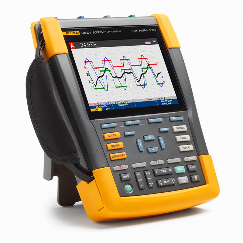


Product Overview: Fluke 190 Series III ScopeMeter® Test Tool
High-performance portable oscilloscope designed for harsh environments
Designed for use in a variety of locations, the Fluke 190 Series III ScopeMeter® Test Tools are ready to tackle any troubleshooting job. These CAT III 1000 V/CAT IV 600V-rated test tools combine rugged portability with high-performance benchtop oscilloscopes to help you easily meet the challenges of installing, commissioning, and maintaining industrial machinery, automation/process control devices, and power conversion electronics from DC to 500 MHz.
Choose from dual- or quad-channel models with a wide range of bandwidth options. Fast sampling rates up to 5.0 GS/s with 200 ps resolution and deep memory for 10,000 samples per channel allow waveform details, noise and other disturbances to be captured and displayed with high accuracy. Make timing or amplitude-dependent measurements on three-phase or three-axis control systems, or compare and contrast multiple test points on the circuit under test. features such as TrendPlot™ paperless recorder, ScopeRecord™ mode, Connect-and-View™ triggering, and a unique 100-screen replay function help you diagnose problems quickly, minimizing maintenance costs and downtime. costs and downtime. These features make the oscilloscope easy to use, especially when diagnosing the most difficult problems, such as complex waveforms, induced noise, intermittent events, and signal fluctuations or drift.
- Up to four independent floating isolated inputs up to 1000 V
- Up to 5 GS/s real-time sample rate (depending on model and channel used)
- Deep memory: 10,000 points per waveform trace capture (oscilloscope mode)
- CAT III 1000 V/CAT IV 600 V safety instruments for industrial environments
- Up to seven hours of battery life thanks to the BP291 battery
- Bright, large color display that is easy to view in almost any environment
- Easy to store and view historical data and transfer to PC via USB or Wifi
- Easy-open and close battery cover for quick battery changes in the field
- Dust and water resistant to IP51
- Connect-and-View triggering for fast, slow, and even complex signals.
- Spectrum analysis using FFT
- 100-screen automatic capture and replay
- ScopeRecord mode provides 30,000 points per input channel for low-frequency signal analysis
- TrendPlot paperless recorder mode with deep memory for long-term automated measurements
- 5,000 count multimeter (DMM) included in 2-channel model

Safe measurement of mV to kV voltage
Separate isolated inputs allow you to make measurements on mixed circuits with different ground references, reducing the risk of accidental short circuits. Conventional benchtop oscilloscopes are not equipped with specialized differential probes and isolation transformers, and can only use the line power ground as the measurement reference. The Fluke 190III Oscilloscope Test Set is designed to cover a wide range of applications from mV to kV, so you can tackle anything from microelectronic applications to heavy-duty, high-voltage electrical applications. 190III 60 MHz and 100 MHz configurations include the VPS421 100:1 Probe for high-voltage applications, while 200 MHz and 500 MHz configurations include the VPS421 100:1 Probe for microelectronic and high-voltage applications. The 200MHz and 500MHz configurations include the VPS410-II 10:1 probe for microelectronics and high voltage applications.
IP-51 rating for harsh environments
The Oscilloscope Test Kit is rugged and vibration resistant for use in dirty, hazardous environments. Comes with a sealed case that protects against dust, liquid droplets, moisture and airborne contamination. You can rest assured that every time you test with your oscilloscope, it will reliably solve any problem you may have.
USB and Wi-Fi connectivity
The Fluke 190 Series III provides two USB ports electrically isolated from the measurement input circuitry, which allows you to quickly and easily transfer data to a PC, archive and share waveforms with OEMs, coworkers, and support personnel, or store waveforms, screenshots, and instrument settings on a USB memory device for future use. Saved files are easily transferred via USB flash drive, which connects directly to the PC via the USB port or optional Wi-Fi network. These files can be used for further data processing or in FlukeView-2 software to study the waveforms in more detail.
Connect-and-View Trigger Functions
Connect-and-View triggering provides an instant, stable display with no need to adjust settings. If you've ever worked with other oscilloscopes, you know how tricky triggering can be. If you don't set it up correctly, results can be erratic or incorrect, and the Connect-and-View feature automatically sets the correct trigger by recognizing signal patterns. Without touching a button, you can display almost any signal, including motor drive and control signals, consistently, reliably, and reproducibly. This is especially fast and convenient when you are measuring a series of test points quickly and continuously.


Built-in digital multimeter
Use the built-in 5000-word digital multimeter on the dual-channel 190III model to make it easy to switch from waveform analysis to accurate multimeter measurements. Measurement functions include Vdc, Vac, Vac+dc, resistance, on-off and diode tests. Combine the right shunt, probe or adapter with a variety of scale factors to measure current and temperature.
ScopeRecord™ mode for recording high-resolution waveforms
The ScopeRecord memory stores up to 30,000 or more data points per channel and captures fast intermittent events and short-duration pulse wave disturbances as short as 8 ns. (Two sets of multi-channel recordings can be stored in memory for later analysis. (Two sets of multi-channel records can be stored in memory for later analysis.)
- Record events such as UPS, power supply or motor start cycles
- ScopeMeter Test Tool automatically recognizes power failures and stores pre-failure waveform data thanks to the "Stop on Trigger" mode.


TrendPlot paperless logger - up to 11 days of logging to help you find intermittent faults
The most difficult faults to find are those that occur occasionally. These intermittent events can be caused by improper connections, dust, dirt, corrosion, broken wires, or broken connectors. Line interruptions, dips, surges and momentary breaks, or motor starts and stops may also cause downtime. You may not be around when these conditions occur, but the Fluke 190 Series III ScopeMeter Test Tool will help you monitor them at all times.
- Display of minimum and maximum peaks and average values over time
- Displays any combination of up to four readings including voltage, current, temperature, frequency and phase for all inputs, all time and date stamped to identify faults
FlukeView2 software for recording, archiving and analyzing
Learn more about the ScopeMeter Test Tool with FlukeView 2 ScopeMeter software for Windows.
- Recording - transfer waveforms, screenshots and data to a PC for printing or importing data into reports
- Adds text to ScopeMeter Test Tool settings - provides guidance to operators when recalling settings
- Archiving - create waveform libraries for easy reference or comparison of waveforms
- Analysis - use cursor functions or export data to another analysis program

| Product Specification: Fluke 190 Series III ScopeMeter® Test Tool | |||||||
|---|---|---|---|---|---|---|---|
| Oscilloscope Mode | |||||||
| 190-062 | 190-102 | 190-202 | 190-502 | 190-104 | 190-204 | 190-504 | |
| vertical deflection | |||||||
| Number of channels | 2 | 2 | 2 | 2 | 4 | 4 | 4 |
| bandwidths | 60 MHz | 100 MHz | 200 MHz | 500 MHz | 100 MHz | 200 MHz | 500 MHz |
| rising time | 5.8 ns | 3.5 ns | 1.7 ns | 0.7 ns | 3.5 ns | 1.7 ns | 0.7 ns |
| Number of oscilloscope inputs | 2 input channels and external trigger | 4 input channels | |||||
| Channel Architecture | All inputs are completely insulated from each other and from the ground. The inputs can be activated in any combination. | ||||||
| Input coupling | AC or DC with ground level indication | ||||||
| Input Sensitivity | 20 mV - 1000 V/gram with 10:1 probe | ||||||
| 200 mV - 10 kV/gram with 100:1 probe | |||||||
| DC (1:1) 2 mV - 100 V/gram | |||||||
| bandwidth limiter | 20 MHz and 10 kHz | ||||||
| polarities | Normal, Reverse, Variable | ||||||
| Input Voltage | CAT III 1000 V/CAT IV 600 V safety class, for more detailed information, see General Specification | ||||||
| vertical resolution | 8-bit | ||||||
| Accuracy (4 s - 10 μs/gram) | 5 mV/gram - 100 V/gram, ± (1.5% + 6 counts) | ||||||
| 2 mV/gram, ± (1.5% + 10 counts) | |||||||
| Input Impedance | 1 MΩ (± 1%) // 15 pF (± 2.25 pF) | ||||||
| horizontal display | |||||||
| Maximum real-time sampling rate (simultaneous sampling) | 625 Ms/s | 1.25 GS/s (per channel) | 2.5 GS/s (per channel) | 5 GS/s (single channel) or | 1.25 GS/s (per channel) | 2.5 GS/s (2ch) | 5 GS/s (single channel) or 2.5 GS/s (dual channel) or 1.25 GS/s (quad channel) |
| (per channel) | 2.5 GS/s (dual channel) | 1.25 GS/s (4ch) | |||||
| Record length | Up to 10,000 samples per channel | ||||||
| Time base range | 10 ns/div | 5 ns/div | 2 ns/div | 1 ns/div | 5 ns/div | 2 ns/div | 1 ns/div |
| to 4 s/div | to 4 s/div | to 4 s/div | to 4 s/div | to 4 s/div | to 4 s/div | to 4 s/div | |
| Time base order is 1-2-4 | |||||||
| Use ScopeRecord™ scrolling mode (see "Recorder Mode" for details) for slower Time/Grid settings. | |||||||
| Maximum record length | In oscilloscope mode, the number of samples per channel is 10,000; | ||||||
| 30,000 points per channel in ScopeRecord™ scrolling mode (see "Recorder Mode" for details) | |||||||
| timing accuracy | ± (0.01% reading + 1 pixel) | ||||||
| Short duration pulse wave interference capture | 8 ns (10 µs/gram to 2 min/gram) | ||||||
| Display and Acquisition | |||||||
| monitor | 133 mm x 90 mm (5.3 in x 3.5 in) full color high brightness LCD | ||||||
| display mode | Channels can be combined in any way, average mode on/off; playback mode. | ||||||
| Visual screen width | 12 horizontal grids in oscilloscope mode | ||||||
| Continuous digital mode | Off, short, medium, long, infinite and envelope modes | ||||||
| Waveform math applications | Performs one (190-xx2) or two (190-x04) math operations on 2 input channels (A and B, C and D): addition, subtraction, multiplication; X-Y mode; FFT analysis of spectra | ||||||
| Acquisition Mode | Normal, Average, Auto, Single Sample, ScopeRecord™ Scrolling, Short Duration Pulse Waveform Interference Capture, Pass/Fail Auto Test Waveform Comparison; Playback | ||||||
| Trigger and delay | |||||||
| signal source | Input A, B or external input (via meter input) | Enter A, B, C, or D | |||||
| paradigm | Auto, Edge, Pulse Width, N-Cycle, External (190-xx2) | ||||||
| Connect-and-View™ | Advanced auto-trigger recognizes signal patterns and automatically sets and continuously adjusts trigger, time base and amplitude. Automatic display of stabilized waveforms for complex and dynamic signals (e.g. motor drive and control signals). It can also be turned off optionally according to personal preference. | ||||||
| Pulse width trigger (on channel A) | Time-limited pulse width | ||||||
| This can be done in the |
|||||||
| time delay | 1 pre-trigger full screen view, or up to 100 post-trigger delayed screens (= 1,200 frames) | ||||||
| Double Slope Trigger | Rising and falling edge similar triggering | ||||||
| N-cycle Trigger | Triggered on the Nth occurrence of the trigger event; N can be set from 2 to 99. | ||||||
| Automatic capture of 100 screens | |||||||
| When in oscilloscope mode, the instrument always stores the last 100 screens - no specific user settings are required. When an anomaly is detected, the Replay button can be pressed to view the full sequence of screen events over and over again. The instrument can be set up for short burst interference triggering or intermittent anomaly triggering, and will run in "caretaker" mode and capture 100 specified events. | |||||||
| replay | Manual or continuous replay. Display 100 captured screens as "live" animation or under manual control. Each screen is date and time stamped. | ||||||
| Replay storage | Two groups of screens (100 each) can be stored internally for later recall and analysis. Store additional groups of screens directly on an external flash drive via the USB host port. | ||||||
| FFT - Spectrum Analysis | |||||||
| Using the Fast Fourier Transform to Display the Frequency Composition of Oscilloscope Waveforms | |||||||
| window function | Automatic, Hemming, Hanning or none | ||||||
| automated window function (math.) | Digitally resample the acquired waveform to obtain the best frequency resolution in the FFT ensemble. | ||||||
| vertical scale | Linear/Logarithmic (in volts or amps) | ||||||
| frequency axis | Frequency range is automatically set as a function of the oscilloscope time base range | ||||||
| Waveform comparison and pass/fail testing | |||||||
| Waveform Comparison | Provides storage and display of a reference waveform for visual comparison with the newly acquired waveform. The reference waveform is derived from the acquired waveform and can be modified on the oscilloscope. | ||||||
| Pass/Fail Tests | In Waveform Compare mode, the oscilloscope can be set to store only matched ("pass") or unmatched ("fail") captured waveforms in the replay memory strip for further analysis. | ||||||
| Oscilloscope Automatic Measurement | |||||||
| V dc, V ac rms, V ac+dc, V (Maximum Peak), V (Minimum Peak), V (Peak-to-peak), A ac, A dc, A ac+dc, Frequency (Hz), Rise Time (with cursor), Fall Time (with cursor), Power Factor (PF), Wattage, VA, Reactive VA, Phase (between the 2 inputs (A&B or C&D)), Pulse Width (positive/negative), Duty Cycle (positive/negative), Temperature °C, Temperature °F (not available for Japan), dBV, dBm (corresponds to 50 Ω and 600 Ω), VPWM ac and VPWM (ac+dc) (for measurements of pulse-width-modulated motor drives and inverters), V/Hz ratio; | |||||||
| Advanced power and motor drive functions | V/Hz Ratio, Power Factor (PF), Watts, VA, Reactive VA, V-PWM (ac), and V-PWM (ac+dc) (for measurement of pulse-width modulated motor drives and inverters) | ||||||
| cursor measurement | |||||||
| signal source | On any input waveform or on a mathematically synthesized waveform (excluding X-Y mode) | ||||||
| bizontal line | Voltage at Cursor 1 and Cursor 2, voltage between cursors | ||||||
| double vertical line | Time between markers, 1/T between markers (in Hz), voltage between markers, rise time with markers, fall time with markers; Vrms between markers, watts between markers. | ||||||
| single vertical line | Minimum-maximum and average voltage at the cursor position, frequency and root mean square of individual frequency components in the FFT ensemble | ||||||
| Advanced Features | mA*s (current over time, between cursors); V*s (voltage over time, between cursors); W*s (energy consumption, between cursors) | ||||||
| resizing | The zoom range is from full record overview zoom to sample level, suitable for any record length. | ||||||
| Instrumentation Mode | |||||||
| 190-062 | 190-102 | 190-202 | 190-502 | 190-104 | 190-204 | 190-504 | |
| Meter Input | Input via 4 mm banana plug, completely isolated from oscilloscope input and ground | Oscilloscope input via BNC | |||||
| Number of readings | Read one at a time through the DMM multimeter inputs | Up to 4 oscilloscope automatic measurements simultaneously | |||||
| highest resolution | 5000 counts | ± 999 counts | |||||
| (Frequency: 9999 counts) | |||||||
| Input Impedance | 1 MΩ (± 1%) // 14 pF (± 1.5 pF) | 1 MΩ (± 1%) // 15 pF (± 2.25 pF) | |||||
| Advanced Meter Functions | Auto/Manual Ranging, Relative Measurement (Zero Reference), TrendPlot™ Recording | ||||||
| The specified accuracy is valid when the temperature range is 18 °C - 28 °C. For temperatures below 18 °C or above 28 °C, the accuracy changes by 10% of the specified accuracy for every 1 °C change in temperature. | |||||||
| input voltage | |||||||
| V dc Accuracy | ± (0.5% + 6 counts) | ± (1.5% + 6 counts) | |||||
| V ac True RMS Accuracy | |||||||
| 15 Hz to 60 Hz | ± (1% + 10 counts) | ± (1.5% + 10 counts) | |||||
| 60 Hz to 1 kHz | ± (2.5% + 15 counts) | - | |||||
| 60 Hz to 20 kHz | - | ± (2.5% + 15 counts) | |||||
| V ac+dc True RMS Accuracy | |||||||
| 15 Hz to 60 Hz | ± (1% + 10 counts) | ± (1.5% + 10 counts) | |||||
| 60 Hz to 1 kHz | ± (2.5% + 15 counts) | - | |||||
| 60 Hz to 20 kHz | - | ± (2.5% + 15 counts) | |||||
| Voltmeter range | 500 mV, 5 V, 50 V, 500 V, 1,100 V | ||||||
| resistive | |||||||
| range (of scales or measuring equipment) | 500 Ω, 5 kΩ, 50 kΩ, 500 kΩ, 5 MΩ, 30 MΩ | - | |||||
| accurate | ± (0.6% + 6 counts) | - | |||||
| Other Meter Functions | |||||||
| intermittence | < 50 Ω (± 30 Ω) Buzzer on | - | |||||
| Diode Testing | Up to 2.8 V | - | |||||
| Current (A) | A dc, A ac, A ac+dc with optional current clamp or shunt Scaling factors: 0.1 mV/A, 1 mV/A - 100 V/A and 400 mV/A | ||||||
| temp | With optional accessories. Scaling factor 1mV/°C or 1mV/°F | ||||||
| Logger Mode | |||||||
| 190-062 | 190-102 | 190-202 | 190-502 | 190-104 | 190-204 | 190-504 | |
| ScopeRecord™ Scroll Mode | |||||||
| Dual or multiple input waveform storage modes using deep memory | |||||||
| Signal sources and displays | Input A, Input B, Dual Input | Any combination of inputs, up to 4 channels. | |||||
| Simultaneous sampling of all channels | Simultaneous sampling of all channels | ||||||
| Storage depth | 30,000 data points per channel with separate minimum/maximum value pairs | ||||||
| Min/Max | Create min/max values for samples measured at high sampling rates to ensure that short duration pulse wave disturbances are captured and displayed. | ||||||
| recording mode | Single-scan, continuous scrolling; on when triggered (via external input); off when triggered (via external input) | Single scan, continuous scrolling; on when triggered (through any channel); off when triggered (through any channel) | |||||
| Stop when triggered | ScopeRecord mode can be via any input channel (external input on 190-XX2 series) | ||||||
| Stopped by a single trigger event or by an interruption of a repeated trigger signal | |||||||
| horizontal scale | Start time, time of day | ||||||
| resizing | Zoom range from full record overview to sample level | ||||||
| random access memory (RAM) | Two multi-input ScopeRecord waveforms can be stored internally for later recall and analysis. | ||||||
| ScopeRecord™ Rolling Mode Sample Rate and Record Time Range | |||||||
| Time base range | 4 ms/frame ~ 2 min/frame | ||||||
| Recording time range | 4.8 seconds ~ 40 hours | ||||||
| Time/Grid in "View All" mode | 0.4 s/gram ~ 4 h/gram | ||||||
| Short duration pulse wave interference capture | 8 ns | ||||||
| sampling rate | 125 MS/s | ||||||
| resolution (of a photo) | 160 microseconds ~ 4.8 seconds | ||||||
| TrendPlot™ records | |||||||
| Multi-channel paperless electronic recorder. Graphically plots, displays and stores the results of up to four automated oscilloscope measurements or DMM readings over time. | |||||||
| Signal sources and displays | Any combination of oscilloscope measurements (on any input channel) or DMM readings (dual-channel instruments) | ||||||
| Storage depth | 19,200 points (groups) are stored per record. Each sample point recorded includes the minimum, maximum, and average values, as well as a date and time stamp. | ||||||
| range (of scales or measuring equipment) | Normal view: 5 sec/frame - 30 min/frame; in View All mode: 5 min/frame - 48 hr/frame (overview of all records) | ||||||
| Recording time range | Up to 22 days with a resolution of 102 seconds; 4 readings up to 5.5 days. | ||||||
| recording mode | Continuous recording from 5 s/division with automatic time scale compression | ||||||
| Measurement speed | 3 or more automatic measurements per second | ||||||
| horizontal scale | Start time, time of day | ||||||
| resizing | Zoom out up to 64 times (to display a full overview of the record) and zoom in up to 10 times (to maximize details) | ||||||
| random access memory (RAM) | Two multi-input TrendPlot records can be stored internally for later recall and analysis. | ||||||
| Cursor measurement - all logger modes | |||||||
| signal source | Arbitrary waveform traces in any waveform display mode (Oscilloscope, ScopeRecord or TrendPlot) | ||||||
| double vertical line | The cursor can be used in conjunction with the Cursor Interval Time, Start Time, or Absolute Time to identify the minimum, maximum, or average value of any data point in the record. | ||||||
| General technical indicators | |||||||
| 190-062 | 190-102 | 190-202 | 190-502 | 190-104 | 190-204 | 190-504 | |
| Input Voltage Range | |||||||
| Rated maximum floating voltage | CAT III 1000 V/CAT IV 600 V (maximum voltage between any contact and ground voltage level) | ||||||
| VPS410-II Probe Input Voltage | CAT III 1000 V/CAT IV 600 V (standard 10:1 maximum voltage between probe tip and reference lead) | ||||||
| VPS421 Probe Input Voltage | CAT III 1000V/CAT IV 600V (maximum voltage between probe tip or reference lead and ground, 2000V maximum between probe tip and reference lead) | ||||||
| Maximum BNC Input Voltage | CAT IV 300 V (maximum voltage for direct BNC input) | ||||||
| Maximum Input Voltage | CAT III 1000 V/CAT IV 600 V | - | |||||
| (Banana type input connector with safety design) | |||||||
| Memory Storage and Recall | |||||||
| Memory location (built-in) | 30 waveform memories, 10 record memories, and 9 screen copy memories | ||||||
| 30 waveform storage | Each memory location can contain up to 2 or 4 waveforms and corresponding settings. | ||||||
| 10 record stores | Each memory location can contain: 100 screen playback sequences, ScopeRecord scrolling mode records (2 or 4 traces), or TrendPlot records for up to 4 measurements. | ||||||
| External data storage | Stored on a PC using FlukeView™-2 software or directly on an external flash drive (up to 32 GB) via the USB host port | ||||||
| screen copy | Stored on a PC using FlukeView™-2 software, or stored internally (in the instrument), screen copies can be copied to an external flash drive as .BMP files via the USB host port | ||||||
| volatility | Saving takes place in non-volatile flash ROM and all data is secure, independent of battery or power status. | ||||||
| real time clock | Provides date and time stamp information for ScopeRecord, 100-screen replay sequences, and TrendPlot records. | ||||||
| housings | |||||||
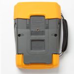
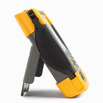
| devise | Rugged and shockproof with a one-piece protective holster. Comes standard with wrist strap and lanyard. | ||||||
| Supports anti-theft locking holes to lock the instrument when unattended. | |||||||
| Waterproof and dustproof | IP 51 protection class according to IEC60529 | ||||||
| Vibration and shock | Shock resistance up to 30 g, vibration resistance (sine) up to 3 g/0.03 g2/Hz (random) per MIL-PRF-28800F Type 2 standard | ||||||
| Display Size | 133 mm x 90 mm (5.3 in x 3.5 in) LCD | ||||||
| resolution (of a photo) | 1120 pixels x 765 pixels | ||||||
| luminance | User adjustable up to 300 cd/m2 | ||||||
| Mechanical data | |||||||
| sizes | 265 mm x 192 mm x 70 mm (10.5 in x 7.6 in x 2.8 in) | ||||||
| Weight (with battery) | 2.1 kg (4.6 lb) | 2.2 kg (4.8 lb) | |||||
| power supply | |||||||
| Line Power | Included BC190/830 Universal Power Adapter/Battery Charger with Detachable 2-Wire Power Cord: 100 Vac to 240 Vac, ±10%, 50-60 Hz | ||||||
| Battery Power | Rechargeable lithium-ion battery (included). Batteries can be replaced with the easy-open battery cover on the back of the instrument | ||||||
| Battery type and capacity included [optional battery] | BP290: 10.8V, 2500 mAh | BP291: 10.8V, 5000 mAh | |||||
| [BP291 (5000 mAh) optional] | |||||||
| Battery level marking | The battery is equipped with a built-in status marker for use with an external charger, located next to the battery status marker on the instrument screen. | ||||||
| Battery life (with low backlight) | Up to 3.5 hours with BP290 (included); up to 7 hours with BP291 (optional) | Up to 7 hours with BP291 (included) | |||||
| Battery charging time | 2½ hours with BP290; 5 hours with BP291 | 5 hours with BP291 | |||||
| Battery saving function | Automatic "power off" with adjustable power off time. Automatic "display off" with adjustable power-off time. | ||||||
| Battery power marking on the screen | |||||||
| safety | |||||||
| compliancy | EN61010-1, pollution class 2; | ||||||
| IEC 61010-2-030: CAT IV 600 V / CAT III 1000 V | |||||||
| Environmental requirements | |||||||
| operating temperature | Battery discharge: 0 °C to 40 °C (32 °F to 104 °F) | ||||||
| Battery charging: 0 °C to 40 °C (32 °F to 104 °F) | |||||||
| storage temperature | -20 °C to 60 °C (-4 °F to 140 °F) | ||||||
| humidity level | 0 °C to 10 °C (32 °F to 50 °F): non-condensing | ||||||
| 10 °C to 30 °C (50 °F to 86 °F): 95 % (±5 %) | |||||||
| 30 °C to 40 °C (86 °F to 104 °F): 75 % (±5 %) | |||||||
| 40 °C to 50 °C (104 °F to 122 °F): 45% (±5%) | |||||||
| Maximum working altitude | CAT IV 600 V, CAT III 1000 V: up to 2000 m (6600 ft) | ||||||
| CAT IV 300 V, CAT III 600 V, CAT II 1000 V: up to 4000 m (13000 ft) | |||||||
| Maximum storage altitude | 12 km (40,000 ft) | ||||||
| Electromagnetic Compatibility (EMC) | IEC 61326-1: Industry; | ||||||
| CISPR 11: Group 1, category A; | |||||||
| Korea (KCC): Class A equipment (industrial broadcasting and communications equipment); | |||||||
| United States (FCC): 47 CFR Part 15, Subpart C. | |||||||
| connector | With two USB ports. The ports are fully insulated from the instrument's floating measurement circuitry. | ||||||
| The USB host port connects directly to external flash memory (up to 32 GB) for storing waveform data, measurements, meter settings, and screen copies. Alternatively, this USB-A port can be used to connect a WiFi adapter for wireless PC connectivity. A Mini-USB-B port is available to allow interconnection to a PC for remote control and data transfer under PC control using FlukeView-2 software. | |||||||
| Probe Calibration Output | Dedicated probe calibration output with reference contact, fully insulated from any measurement input channel. | ||||||
| Generator output: 1.225 Vpp/500 Hz square wave | |||||||
| warranty period | 3 years for main instrument, 1 year for batteries and accessories | ||||||
| kit | |||||||
| Battery Charger/Power Adapter | BC190/830 | ||||||
| Lithium-ion battery packs | BP290 (10.8V, 2500 mAh) | BP291 (10.8V, 5000 mAh) | |||||
| Voltage probe sets. Each set includes a grounding lead, hook clip; the VPS410-II-x also has a grounding spring and probe tip insulation sleeve. | 2 VPS421-x Reinforced Industrial Grade Probes, 100:1, 150MHz, with Sheathed 4mm Banana Tip and Large Jaw Alligator Clips (one red, one blue) | 2 VPS410-II-x 10:1 Voltage Probes, 500 MHz (one red, one blue) | 4 VPS421-x Reinforced Probes, 100:1, 150 MHz, (red, blue, gray, green) | 4 VPS410-II-x 10:1 Voltage Probes, 500 MHz (one red, one gray, one blue, one green) | |||
| Test Leads | TL175 (one red, one black) with test pins | - | |||||
| (sth. or sb) else | Lithium-ion battery (BP290 or BP291, see above); battery charger (BC190) with universal power cord kit; lanyard; wrist strap (user selectable for left- or right-handed use); downloadable information about the user manual and FlukeView®-2 Demo Package (limited functionality); and USB interface cable for PC connection. Feed-through cable terminator, 50 Ω (one per channel, 190-50x only). | ||||||
| Optional Configurations | Each model is available "in the box" (as described above) or with the optional SCC293 kit, which includes the CXT293 Reinforced Protective Carrying Case, the full version of the FlukeView PC software (with activation code), and a WiFi adapter for wireless PC connectivity using the FlukeView-2 software. SCC293 kit.) | ||||||
| Optional Accessories | SCC293, VPS101 - 1:1 Voltage Probe; VPS510-x - Wideband Compact Probe; i400s Current Clamp; HH290 Hanger; CXT293 Protective Carrying Case; TRM50-BNC Feed-Through Cable Terminator, 50 Ω, Secure Design; EBC290 Battery Charging Cradle | ||||||
Model: Fluke 190 Series III ScopeMeter® Test Tool
ScopeMeter 190-062-III Test Tool
upc#: 1 95112 02177 4
Attached:
- ScopeMeter 190-062-III
- Power Adapter Model BC190/830
- power cable set
- BP290 Lithium-ion Battery Pack
- TL175 Test Lead Set
- VPS421 Probe (2x)
- wristband
- sling
- USB Cable
- Printing instructions
ScopeMeter 190-102-III Test Tool
upc#: 1 95112 02179 8
Attached:
- ScopeMeter 190-102-III
- Power Adapter Model BC190/830
- power cable set
- BP290 Lithium-ion Battery Pack
- TL175 Test Lead Set
- VPS421 Probe (2x)
- wristband
- sling
- USB Cable
- Printing instructions
ScopeMeter 190-104-III Test Tool
upc#: 1 95112 02182 8
Attached:
- ScopeMeter 190-104-III
- Power Adapter Model BC190/830
- power cable set
- BP291 Lithium-ion Battery Pack
- VPS421 Probe (4x)
- wristband
- sling
- USB Cable
- Printing instructions
ScopeMeter 190-202-III Test Tool
upc#: 1 95112 02184 2
Attached:
- ScopeMeter 190-202-III
- Power Adapter Model BC190/830
- power cable set
- BP290 Lithium-ion Battery Pack
- TL175 Test Lead Set
- VPS410-II Probe (2x)
- wristband
- sling
- USB Cable
- Printing instructions
ScopeMeter 190-204-III Test Tool
upc#: 1 95112 02186 6
Attached:
- ScopeMeter 190-204-III
- Power Adapter Model BC190/830
- power cable set
- BP291 Lithium-ion Battery Pack
- VPS410-II Probe (4x)
- wristband
- sling
- USB Cable
- Printing instructions
ScopeMeter 190-502-III Test Tool
upc#: 1 95112 02188 0
Attached:
- ScopeMeter 190-502-III
- Power Adapter Model BC190/830
- power cable set
- BP291 Lithium-ion Battery Pack
- TL175 Test Lead Set
- VPS410-II Probe (2x)
- wristband
- sling
- USB Cable
- TRM50 Cable Terminator (2 pcs)
- Printing instructions
ScopeMeter 190-504-III Test Tool
upc#: 1 95112 02190 3
Attached:
- ScopeMeter 190-504-III
- Power Adapter Model BC190/830
- power cable set
- BP291 Lithium-ion Battery Pack
- VPS410-II Probe (4x)
- wristband
- sling
- USB Cable
- TRM50 Cable Terminator (4 pcs)
- Printing instructions
ScopeMeter 190-062-III/S Test Tool with kit
upc#: 1 95112 02178 1
Attached:
- ScopeMeter 190-062-III
- Power Adapter Model BC190/830
- power cable set
- BP290 Lithium-ion Battery Pack
- TL175 Test Lead Set
- VPS421 Probe (2x)
- wristband
- sling
- USB Cable
- CXT293 Carrying Case
- DWA-131 WiFi Adapter
- FlukeView Activation Manual (paper)
- Printing instructions
ScopeMeter 190-102-III/S Test Tool with kit
upc#: 1 95112 02180 4
Attached:
- ScopeMeter 190-102-III
- Power Adapter Model BC190/830
- power cable set
- BP290 Lithium-ion Battery Pack
- TL175 Test Lead Set
- VPS421 Probe (2x)
- wristband
- sling
- USB Cable
- CXT293 Carrying Case
- DWA-131 WiFi Adapter
- FlukeView Activation Manual (paper)
- Printing instructions
ScopeMeter 190-104-III/S Test Tool with kit
upc#: 1 95112 02183 5
Attached:
- ScopeMeter 190-104-III
- Power Adapter Model BC190/830
- power cable set
- BP291 Lithium-ion Battery Pack
- VPS421 Probe (4x)
- wristband
- sling
- USB Cable
- CXT293 Carrying Case
- DWA-131 WiFi Adapter
- FlukeView Activation Manual (paper)
- Printing instructions
ScopeMeter 190-202-III/S Test Tool with Kit
upc#: 1 95112 02185 9
Attached:
- ScopeMeter 190-202-III
- Power Adapter Model BC190/830
- power cable set
- BP290 Lithium-ion Battery Pack
- TL175 Test Lead Set
- VPS410-II Probe (2x)
- wristband
- sling
- USB Cable
- CXT293 Carrying Case
- DWA-131 WiFi Adapter
- FlukeView Activation Manual (paper)
- Printing instructions
ScopeMeter 190-204-III/S Test Tool with Kit
upc#: 1 95112 02187 3
Attached:
- ScopeMeter 190-204-III
- Power Adapter Model BC190/830
- power cable set
- BP291 Lithium-ion Battery Pack
- VPS410-II Probe (4x)
- wristband
- sling
- USB Cable
- CXT293 Carrying Case
- DWA-131 WiFi Adapter
- FlukeView Activation Manual (paper)
- Printing instructions
ScopeMeter 190-502-III/S Test Tool with Kit
upc#: 1 95112 02189 7
Attached:
- ScopeMeter 190-502-III
- Power Adapter Model BC190/830
- power cable set
- BP291 Lithium-ion Battery Pack
- TL175 Test Lead Set
- VPS410-II Probe (2x)
- wristband
- sling
- USB Cable
- TRM50 Cable Terminator (2 pcs)
- CXT293 Carrying Case
- DWA-131 WiFi Adapter
- FlukeView Activation Manual (paper)
- Printing instructions
ScopeMeter 190-504-III/S Test Tool with Kit
upc#: 1 95112 02191 0
Attached:
- ScopeMeter 190-504-III
- Power Adapter Model BC190/830
- power cable set
- BP291 Lithium-ion Battery Pack
- VPS410-II Probe (4x)
- wristband
- sling
- USB Cable
- TRM50 Cable Terminator (4 pcs)
- CXT293 Carrying Case
- DWA-131 WiFi Adapter
- FlukeView Activation Manual (paper)
- Printing instructions

