 Comprehensive test and measurement service provider-Shenzhen Weike Electronic Technology Co.
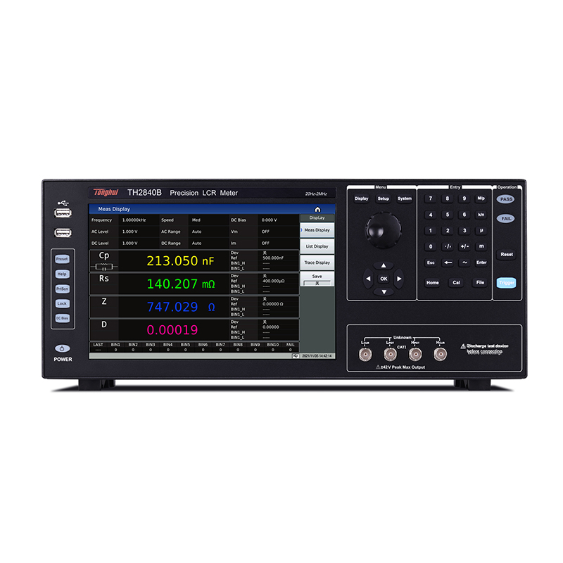
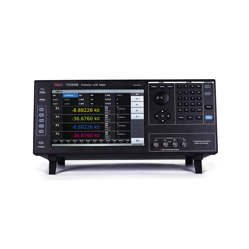


A.10.1-inch large screen with four measurement parameters for details at a glance
10.1-inch touch screen, 1280 * 800 resolution, Linux system, Chinese and English operating interface, support for keyboard, mouse, LAN interface, brings unparalleled operational convenience
Sex.
The large screen offers the added benefit of being able to place four test parameters and sorting parameters, sorting results, function selections, etc. on the same screen and never look crowded.
Crowding and clutter, at the same time can display four kinds of measurement parameters, four kinds of measurement parameters arbitrarily adjustable.
The ease of operation and completeness of the display are readily apparent when compared to earlier LCRs.


B. Up to 1800 times/second measurement speed
Thanks to the innovative dual-CPU design, where one CPU is responsible for test processing data and the other for displaying data, the TH2840 test speed is up to 1,800 times/second.
High test speeds can greatly improve efficiency in automated production lines.
For part of the need for real-time sampling to reflect the characteristics of the transient changes in the measured part, or to measure the corresponding time of the change process, the TH2840 series of 0.56ms measurement speed can be a perfect solution.
As in the following application, a bias voltage is loaded between two polar plates and the capacitance at both ends varies with the bias voltage.
Record the capacitance C0 when no bias is applied.
Capacitance value during bias rise
Capacitor C1 after bias voltage reaches 20V and stabilized
Calculate the stabilization time Th from C0-C1.
Conventional LCR digital bridges, due to test speed limitations, are unable to reach sampling rates of a few![]()
Almost real-time acquisition, with TH2840 series dual CPU, can observe the change process and calculate in real time.
Out of stabilization time.

![]()
TH2840X Uplink Oscilloscope Real-time Waveform Capture


Capacitance test CH1: AD pulse (yellow)
Test frequency: 1MHz CH2: DC BIAS on (green)
Range: 100Ω CH4: DC BIAS rising (red)


Rise instant waveform All waveforms
C.Superb Hardware Configuration
In addition to the dual CPU design, the TH2840 series also enhances other hardware configuration parameters:
1. AC test level is increased to 20Vrms/100mA, which can only be achieved by TH2838H, and the range is wider when testing C-V curve.
2. DC bias is ±40V/±100mA, which is the highest configuration of the same kind of products.
3. Standard with independent 2A DC bias current source, for inductance test within 2A current brings the gospel, support the external TH1778A series expansion to 120A.
4. DCR test level increased to 20V, test mH class and above inductors more quickly and stably accurate.

D. Improved sorting settings
For previous LCR sorting setups and reference setups
switching back and forth and other overly complex operations, making the
The following improvements have been made to facilitate customer use and setup:
1. Combined nominal and reference value settings
2. As a result of the direct application of the 4-parameter measurement and the
The sub-selection, and therefore the elimination of the subsidiary file, the Deputy Senate
Counting files.

E.Enhanced list scanning function F. Powerful graphical interface for analysis
4 measurement parameters can be set, 4 measurement parameters have independent switches, list sweep 4 scanning tracks, 1-4 test parameters can be selected arbitrarily, the scanning curve can be
The frequency, level, bias, function and delay time of each point can be set independently to meet the requirements of split-screen, two-screen and four-screen.
most of our customers' needs.


G. 10-speed sorting and programmable HANDLER interface
The instrument provides 10 grades of sorting, which provides the customer with the possibility to grade the quality of the product How to configure the HANDLER interface when connecting to automation equipment
The TH2840 series of LCRs will be able to output the sorting results directly to the HANDLER interface. output, which has always been a problem for automation customers, the TH2840 series LCR will
HANDLER interface pinout, input/output mode, corresponding signal, answer mode
etc. are fully visualized, making automated connections easier.


H.Intelligent firmware upgrade method
The instrument itself can be updated by upgrading the firmware without returning to the factory for function improvement, bug solution, function upgrade, and so on.
TH2840 series LCR digital bridge firmware upgrade is very intelligent, can be carried out through the system setup interface or file management interface, intelligent search instrument memory, external USB flash drive
Even LAN upgrade packages with automatic upgrades.

I. Optional accessories

| Product Model | TH2840A | TH2840B | ||
|
demonstrate |
monitor (computer) | 10.1-inch capacitive touch screen | ||
| proportions | 16:9 | |||
| resolution (of a photo) | 1280×RGB×800 | |||
|
measured parameter |
way (of life) | Four parameters can be selected arbitrarily | ||
| AC | Cp/Cs, Lp/Ls, Rp/Rs, |Z|, |Y|, R, X, G, B, θ, D, Q, VAC, IAC | |||
| DC | RDC, VDC, IDC | |||
|
Test Frequency |
realm | 20Hz-500kHz | 20Hz-2MHz | |
| accurate | 0.01% | |||
|
resolution (of a photo) |
0.1mHz (20.0000Hz-99.9999Hz) | |||
| 1mHz (100.000Hz-999.999Hz) | ||||
| 10mHz (1.00000kHz-9.99999kHz) | ||||
| 100mHz (10.0000kHz-99.9999kHz ) | ||||
| 1Hz (100.000kHz-999.999kHz) | ||||
| 10Hz (1.00000MHz-2.00000MHz) | ||||
|
AC Test Signal Mode |
Rated value (ALC OFF) | The set voltage is the Hcur voltage when the test terminal is open circuit | ||
| The set current is the current from Hcur when the test terminal is short-circuited. | ||||
| Constant value (ALC ON) | Keep the voltage on the DUT the same as the set value | |||
| Keep the current on the DUT the same as the set value | ||||
|
test level |
voltage range | 5mVrms-20Vrms | F≤1MHz 5mVrms-20Vrms
F>1MHz 5mVrms-15Vrms |
|
| accuracy | ± (10% x setpoint + 2mV) (AC ≤ 2Vrms)
± (10% x setpoint + 5mV) (AC > 2Vrms) |
|||
|
resolution (of a photo) |
1mVrms (5mVrms-0.2Vrms) | |||
| 1mVrms (0.2Vrms-0.5Vrms) | ||||
| 1mVrms(0.5Vrms-1Vrms) | ||||
| 10mVrms (1Vrms-2Vrms) | ||||
| 10mVrms (2Vrms-5Vrms) | ||||
| 10mVrms (5Vrms-10Vrms) | ||||
| 10mVrms(10Vrms-20Vrms) | ||||
| current range | 50μArms-100mArms | |||
|
Resolution (100Ω internal resistance) |
10μArms (50μArms-2mArms) | |||
| 10μArms (2mArms-5mArms) | ||||
| 10μArms (5mArms-10mArms) | ||||
| 100μArms (10mArms-20mArms) | ||||
| 100μArms (20mArms-50mArms) | ||||
| 100μArms (50mArms-100mArms) | ||||
|
RDC Testing |
voltage range | 100mV-20V | ||
| resolution (of a photo) | 1mV(0V-1V) | |||
| 10mV(1V-20V) | ||||
| current range | 0mA-100mA | |||
| resolution (of a photo) | 10μA(0mA-10mA) | |||
| 100μA (10mA-100mA) | ||||
|
DC Bias |
voltage range | 0V-±40V | ||
| accuracy | AC≤2V 1%×set voltage+5mV | |||
| AC>2V 2% x set voltage +8mV | ||||
| resolution (of a photo) | 1mV(0V-1V) | |||
| 10mV (±1V- ±40V) | ||||
| current range | 0mA-±100mA | |||
| resolution (of a photo) | 10μA(0mA-10mA) | |||
| 100μA (10mA-100mA) | ||||
| Built-in current source | current range | 0mA-2A | ||
| accuracy | I>5mA ± (2% x setpoint + 2mA) | |||
| resolution (of a photo) | 1mA | |||
| Test Side Configuration | hand in hand with | |||
| Test cable length | 0m, 1m, 2m, 4m | |||
| Output Impedance | 30Ω, ±4%@1kHz | |||
| 100Ω, ±2%@1kHz | ||||
| mathematical operation | Absolute deviation from nominal value Δ, percentage deviation from nominal value Δ% | |||
| equivalence mode | Series, parallel | |||
| calibration function | Open OPEN, Short SHORT, Load LOAD | |||
| Measured average | 1-255 times | |||
| Range Selection | Auto AUTO, Manual HOLD | |||
| Range Configuration | LCR | 100mΩ, 1Ω, 10Ω, 20Ω, 50Ω, 100Ω, 200Ω, 500Ω, 1kΩ, 2kΩ, 5kΩ, 10kΩ, 20kΩ, 50kΩ, 100kΩ | ||
| RDC | 1Ω, 10Ω, 20Ω, 50Ω, 100Ω, 200Ω, 500Ω, 1kΩ, 2kΩ, 5kΩ, 10kΩ, 20kΩ, 50kΩ, 100kΩ | |||
|
Measurement time (ms) |
Fast+:0.56ms
Fast:3.3ms Medium speed: 90ms Slow: 220ms |
|||
| Maximum accuracy | 0.05% (refer to specifications) | |||
| Measurement display range | ||||
| Cs, Cp | 0.00001pF-9.99999F | |||
| Ls, Lp | 0.00001μH-99.9999kH | |||
| D | 0.00001-9.99999 | |||
| Q | 0.00001-99999.9 | |||
| r, rs, rp, x, z, rdc | 0.001mΩ-99.9999MΩ | |||
| G, B, Y | 0.00001μs-99.9999S | |||
| VDC | ±0V-±999.999V | |||
| IDC | ±0A-±999.999A | |||
| θr | -3.14159-3.14159 | |||
| θd | -179.999°-179.999° | |||
| Δ% | ± (0.000%-999.9%) | |||
|
Multi-function parameter list scanning |
check numbers | 201 points, each point can be set the average number of times, each point can be separate sorting | ||
| parameters | Test Frequency, AC Voltage, AC Current, DC BIAS Voltage, DC BIAS Current (100mA), DC BIAS Current (2A) | |||
|
Trigger Mode |
Sequential SEQ: When triggered once, measurements are taken at all scan points, /EOM/INDEX is output only once | |||
| Step STEP: Performs one scan point measurement per trigger and outputs /EOM/INDEX at each point, but list scan comparator results are only output at the last /EOM | ||||
| Other features | 1. Scanning parameters and test parameters have a variety of copy functions
2. Each scanning point can be set up delay time |
|||
| comparator | Each scanning point can measure up to four test parameters, each parameter can be set upper and lower limits, all test parameters are qualified to output PASS signal, otherwise output FAIL signal, not set upper and lower limits are not judged | |||
|
Graphic Scanning |
Scanning Points | Points 51, 101, 201, 401, 801 are optional | ||
| The results show that | Extreme values for each parameter and the scanned parameter value at the point where the cursor is located with the corresponding test parameter value | |||
| scanning track | 1-4 test parameters can be selected arbitrarily, and the scanning curve can be divided into one screen, two screens and four screens. | |||
| Display range | Real-time automatic, locked | |||
| coordinate scale | Logarithmic, linear | |||
| scanning parameter | Frequency, AC voltage, AC current, DCV BIAS / DCI BIAS(100mA) / DCI BIAS(2A) | |||
| trigger method | one-off | Trigger manually once, one scan from start to finish is completed, the next trigger signal starts a new scan | ||
| progression | Infinite loop scanning from start to finish | |||
| Results Saving | Graphics, documentation | |||
|
comparator |
Bin Staging | 10Bin, PASS, FAIL | ||
| Bin deviation setting | Deviation value, percent deviation value, off | |||
| Bin mode | Tolerance, continuous | |||
| Bin Count | 0-99999 | |||
| grade differentiation | Each file can set up to four parameter limit range, four test parameter results within the set file display corresponding file number, beyond the set maximum file number range will display FAIL, not set the upper and lower limits of the test parameters are automatically ignored file discrimination | |||
| PASS/FAIL indication | If Bin1-10 is met, the front panel PASS light is on, otherwise the FAIL light is on. | |||
| data cache | 201 measurements can be read in batches | |||
| store a call (computing) | inside (part, section) | Approx. 100M non-volatile memory test setup file | ||
| External USB | Test setup files, screenshot graphics, log files | |||
| Keyboard Lock | Lockable front panel keys, other functions to be expanded | |||
|
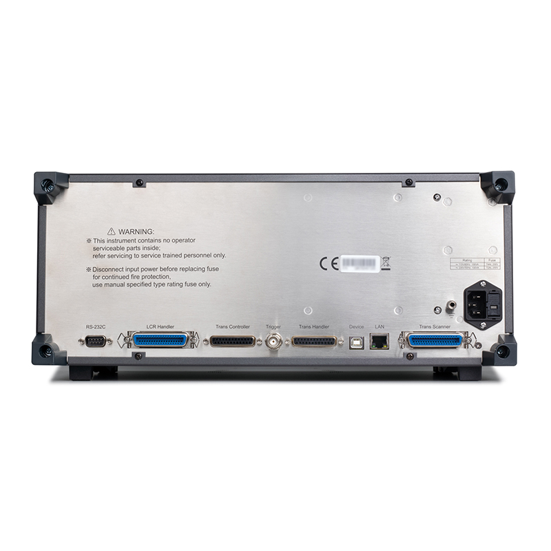
connector |
USB HOST | 2 USB HOST ports, can be connected to the mouse, keyboard, U disk at the same time can only use a | ||
| USB DEVICE | Universal Serial Bus socket, small Class B (4 contact positions); USB TMC-USB488 and USB2.0 compliant, female connector for connection to external controller. | |||
| LAN | 10/100M Ethernet Adaptive | |||
| HANDLER | For Bin Staging Signal Output | |||
| External DC BIAS control | Support TH1778A | |||
| RS232C | Standard 9-pin, Crossed | |||
| RS485 | Accept conversion or external RS232 to RS485 module | |||
| Power-on warm-up time | 60 minutes. | |||
| Input Voltage | 100-120VAC/198-242VAC selectable, 47-63Hz | |||
| power wastage | Not less than 130VA | |||
| Dimensions (WxHxD) mm3 | 430x177x265 | |||
| Weight (kg) | 11kg | |||
■ High resolution: 10.1 inches, resolution 1280*800, capacitive touch screen
■ High stability and consistency: 14 range configurations
■ High power: signal level: 20V/100mA
Built-in DC bias: ±40V/100mA
Built-in bias current source: 2A
■ DCR level: 20V/100mA
■ High speed: dual CPU architecture, the fastest test speed up to 1800 times / s
■ Three types of tests: point test, list scan, and graphic scan
■ Four-parameter measurements
■ 201-point multi-parameter list scanning function
■ Graphic scanning function, 4 tracks optional, support 1/2/4 split screen
■ Sorting function: LCR mode 10-speed sorting
■ High compatibility: supports the SCPI/MODBUS command set.
Compatible with KEYSIGHT E4980A, E4980AL, HP4284A
■ Passive components:
Capacitors, Inductors, Cores, Resistors, Piezoelectric Devices, Transformers, Chip Assemblies and
Evaluation of impedance parameters and performance analysis of network components, etc.
■ Semiconductor components:
Test and analysis of parasitic parameters of LED driver integrated circuits; C-VDC characteristics of varactor diodes
Sex; Parasitic parameter analysis of transistors or integrated circuits
■ Other components:
Impedance evaluation of printed circuit boards, relays, switches, cables, batteries, etc.
■ Medium material:
Evaluation of dielectric constants and loss angles of plastics, ceramics and other materials
■ Magnetic materials:
Evaluation of permeability and loss angle of ferrites, amorphous and other magnetic materials
■ Semiconductor materials:
Dielectric Constant, Conductivity and C-V Characteristics of Semiconductor Materials Liquid Crystal Materials: Liquid Crystal Units of
C-V properties such as dielectric constant, elasticity constant, etc.
■ Various sensors.
Electronic skin, galvanometer image filter array sensor
| standard equipment | |||||
| Accessory Name | model number | ||||
| Boxed Four-Ended Insulated Locking Kelvin Test Leads | TH26011BS | ||||
| fixture (machining) | TH26048 | ||||
| short circuit board | TH26010 | ||||
Recommended


