 Comprehensive test and measurement service provider-Shenzhen Weike Electronic Technology Co.
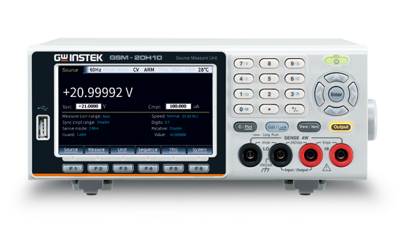
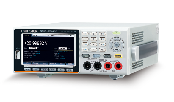
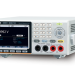


The GSM-20H10 provides ±210V / ±1.05A / 22W four-quadrant operation. In the first and third quadrants, they operate as power supplies to power the load. In the second and fourth quadrants, they operate as loads, dissipating power internally. Voltage, current and resistance values can be measured during power or load operation with an accuracy of 0.012% and a resolution of 1µV/10pA/10µΩ.
The GSM-20H10 supports a sampling speed of up to 50k points per second, which allows for more accurate analysis of the properties of the object to be measured. The large 4.3-inch screen displays all measurement settings, parameters and results. Support SDM (Source Delay Measure) function, which can be set to delay sampling when the signal changes, avoiding the signal before stabilization to be captured in and cause misjudgment. Built-in four program output modes (Linear, Log, SRC-MEM, Custom) can support up to 2500 points of program change output.
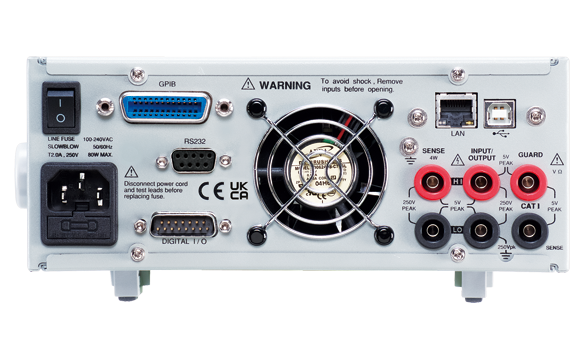
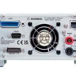
In terms of device protection, GSM-20H10 provides OVP/OTP protection modes; in the design of OVP, users can customize the range of OVP, while the OTP protection can effectively prevent errors caused by temperature offset during the testing process. In the interface section, this product supports standard SCPI commands and provides RS-232 , USBTMC , LAN, GPIB (optional) and other interfaces to meet the different interface needs of users.
Product Specification
| Maximum Range | Voltage | ±210V | ||||||||
| Current | ±1.05A | |||||||||
| Power | 22W | |||||||||
| Voltage Resolution | 1µV | |||||||||
| Current Resolution | 10pA | |||||||||
| Source | DC Voltage | Output Voltage | ±21V/ ±1.05A, ±210V/±105 mA | |||||||
| Current Limit | Min. 0.1% of range | |||||||||
| Programming Resolution | 1µV, ±200.000mV range | |||||||||
| 10µV, ±2.00000V range | ||||||||||
| 100µV, ±20.0000V range | ||||||||||
| 1mV, ±200.000V range | ||||||||||
| Programming Accuracy 1 | ±(0.02%+600µV), ±200.000mV range | |||||||||
| ±(0.02%+600µV), ±2.00000V range | ||||||||||
| ±(0.02%+2.4mV), ±20.0000V range | ||||||||||
| ±(0.02%+24mV), ±200.000V range | ||||||||||
| Load Regulation | 0.01% of range + 100µV | |||||||||
| Line Regulation | 0.01% of range | |||||||||
| Overshoot | <0.1% typical (full scale step, resistive load,10mA range) | |||||||||
| Recovery Time (1000%Load Change) | <250µs (within 0.1% plus load regulation errors, 1A and 100mA compliance.) | |||||||||
| Ripple and Noise | 4mV rms(20Hz~ 1MHz) 10mVpp(20Hz~ 1MHz) | |||||||||
| Temperature Coefficient (0°-18°C & 28°-50°C) |
±(0.15 × accuracy specification)/°C | |||||||||
| DC Current | Output Current | ±1.05A / ±21V, ±105 mA / ±210V | ||||||||
| Voltage Limit | Min. 0.1% of range | |||||||||
| Programmed Source Resolution | 10pA, ±1.00000µA range | |||||||||
| 100pA, ±10.0000µA range | ||||||||||
| 1nA, ±100.000µA range | ||||||||||
| 10nA, ±1.00000mA range | ||||||||||
| 100nA, ±10.00000mA range | ||||||||||
| 1µA, ±100.000mA range | ||||||||||
| 10µA, ±1.00000A range | ||||||||||
| Programmed Source Accuracy 1 | ±(0.035%+600pA), ±1.00000µA range | |||||||||
| ±(0.033%+2nA), ±10.0000µA range | ||||||||||
| ±(0.031%+20nA), ±100.000µA range | ||||||||||
| ±(0.034%+200nA), ±1.00000mA range | ||||||||||
| ±(0.045%+2µA), ±10.00000mA range | ||||||||||
| ±(0.066%+20µA), ±100.000mA range | ||||||||||
| ±(0.27%+900µA), ±1.00000A range | ||||||||||
| Load Regulation | 0 0.01% of range + 100pA | |||||||||
| Line Regulation | 0.01% of range | |||||||||
| Overshoot | <0.1% typical (1mA step, RL = 10kΩ, 20V range). | |||||||||
| Temperature Coefficient (0°-18°C & 28°-50°C) |
±(0.15 × accuracy specification)/°C | |||||||||
| General | Output Settling Time2 | 100µs typical Time | ||||||||
| Output Rise Time (±30%) | 300µs, 200V range, 100mA compliance. | |||||||||
| 150V/µs, 20V range, 100mA compliance. | ||||||||||
| DC Floating Voltage | Output can be floated up to ±250VDC | |||||||||
| Remote Sense | Up to 1V drop per load lead. | |||||||||
| Compliance Accuracy | Add 0.3% of range and ±0.02% of reading to base specification. | |||||||||
| Range Change Overshoot 3 | Adjacent range changes between 200mV, 2V and 20V ranges, 100mV typical. | |||||||||
| Minimum Compliance Value | 0.1% of range | |||||||||
| Command Processing Time 4 | Autorange On:10ms.Autorange Off:7ms. | |||||||||
| Measurement | Voltage | Input Resistance | >10 GΩ | |||||||
| Measurement Resolution | 1µV, ±200.000mV range | |||||||||
| 10µV, ±2.00000V range | ||||||||||
| 100µV, ±20.0000V range | ||||||||||
| 1mV, ±200.000V range | ||||||||||
| Measurement Accuracy | ±(0.012%+300µV), ±200.000mV range | |||||||||
| ±(0.012%+300µV), ±2.00000V range | ||||||||||
| ±(0.015%+1.5mV), ±20.0000V range | ||||||||||
| ±(0.015%+10mV), ±200.000V range | ||||||||||
| Temperature Coefficient (0°-18°C & 28°-50°C) |
±(0.15 × accuracy specification)/°C | |||||||||
| Current | Voltage Burden (4-wire mode) | < 1mV | ||||||||
| Programmed Source Resolution | 10pA, ±1.00000µA range | |||||||||
| 100pA, ±10.0000µA range | ||||||||||
| 1nA, ±100.000µA range | ||||||||||
| 10nA, ±1.00000mA range | ||||||||||
| 100nA, ±10.00000mA range | ||||||||||
| 1µA, ±100.000mA range | ||||||||||
| 10µA, ±1.00000A range | ||||||||||
| Programmed Source Accuracy1 | ±(0.029%+300pA)), ±1.00000µA range | |||||||||
| ±(0.027%+700pA), ±10.0000µA range | ||||||||||
| ±(0.025%+6nA), ±100.000uA range | ||||||||||
| ±(0.027%+60nA), ±1.00000mA range | ||||||||||
| ±(0.035%+600nA), ±10.00000mA range | ||||||||||
| ±(0.055%+6µA), ±100.000mA range | ||||||||||
| ±(0.22%+570µA), ±1.00000A range | ||||||||||
| Temperature Coefficient (0°-18°C & 28°-50°C) |
±(0.1 × accuracy specification) / °C | |||||||||
| Resistance | Range | Resolution | Test current | Accuracy | ||||||
| <2.00000Ω | --- | --- | Source IACC+Meas.VACC | |||||||
| 2.00000Ω | 10µΩ | --- | Source IACC+Meas.VACC | |||||||
| 20.0000Ω | 100µΩ | 100mA | ±(0.1%+0.003 Ω), Normal | |||||||
| ±(0.07%+0.001 Ω), Enhanced | ||||||||||
| 200.000Ω | 1mΩ | 10mA | ±(0.08%+0.03 Ω), Normal | |||||||
| ±(0.05%+0.01 Ω), Enhanced | ||||||||||
| 2.00000kΩ | 10mΩ | 1mA | ±(0.07%+0.3 Ω), Normal | |||||||
| ±(0.05%+0.1 Ω), Enhanced | ||||||||||
| 20.0000kΩ | 100mΩ | 100µA | ±(0.06%+3 Ω), Normal | |||||||
| ±(0.04%+1 Ω), Enhanced | ||||||||||
| 200.000kΩ | 1Ω | 10µA | ±(0.07%+30 Ω), Normal | |||||||
| ±(0.05%+10 Ω), Enhanced | ||||||||||
| 2.00000MΩ | 10Ω | 5µA | ±(0.11%+300 Ω), Normal | |||||||
| ±(0.05%+100 Ω), Enhanced | ||||||||||
| 20.0000MΩ | 100Ω | 0.5µA | ±(0.11%+1k Ω), Normal | |||||||
| ±(0.05%+500 Ω), Enhanced | ||||||||||
| 200.000MΩ | 1kΩ | 100nA | ±(0.66%+10k Ω), Normal | |||||||
| ±(0.35%+5k Ω), Enhanced | ||||||||||
| >200.000M Ω | --- | --- | Source IACC+Meas.VACC | |||||||
| Temperature Coefficient (0°-18°C & 28°-50°C) |
±(0.15 × accuracy specification)/°C | |||||||||
| Source I mode, Manual OHMS | Total uncertainty = I source accuracy + V measure accuracy (4-wire remote sense). | |||||||||
| Source V mode, Manual OHMS | Total uncertainty = V source accuracy + I measure accuracy (4-wire remote sense). | |||||||||
| 6-wire OHMS mode | Available using active ohms guard and guard sense. Max. guard Output Current: 50mA (except 1A range). Accuracy is load dependent. | |||||||||
| Guard Output Impedance | <0.1Ω in ohms mode | |||||||||
| System Speed | Maximum Range Change Rate | 75/second | ||||||||
| Maximum Measure Auto Range Time | 40ms (fixed source) 6 | |||||||||
| Sequence reading rates7 (rdg./second) for 60Hz (50Hz) | Speed | NPLC/ Trig Origin | Measure | Source-Measure 9 | ||||||
| TO MEM. | TO GPIB | TO MEM. | TO GPIB | |||||||
| Fast | 0.01 / internal | 2081 (2030) | 1198 (1210) | 1551 (1515) | 1000 (900) | |||||
| 488.2 | 0.01 / external | 1239 (1200) | 1079 (1050) | 1018 (990) | 916 (835) | |||||
| Medium | 0.1 / internal | 510 (433) | 509 (433) | 470 (405) | 470 (410) | |||||
| 488.2 | 0.1 / external | 438 (380) | 438 (380) | 409 (360) | 409 (365) | |||||
| Normal | 1 / internal | 59 (49) | 59 (49) | 58 (48) | 58 (48) | |||||
| 488.2 | 1 / external | 57 (48) | 57 (48) | 57 (48) | 57 (47) | |||||
| Speed | NPLC/ Trig Origin | Source-Measure Pass/Fail test 8,9 | Measure Memory 9 | |||||||
| TO MEM. | TO GPIB | TO MEM. | TO GPIB | |||||||
| Fast | 0.01 / internal | 902 (900) | 809 (840) | 165 (162) | 164 (162) | |||||
| 488.2 | 0.01 / external | 830 (830) | 756 (780) | 163 (160) | 162 (160) | |||||
| Medium | 0.1 / internal | 389 (343) | 388 (343) | 133 (126) | 132 (126) | |||||
| 488.2 | 0.1 / external | 374 (333) | 374 (333) | 131 (125) | 131 (125) | |||||
| Normal | 1 / internal | 56 (47) | 56 (47) | 44 (38) | 44 (38) | |||||
| 488.2 | 1 / external | 56 (47) | 56 (47) | 44 (38) | 44 (38) | |||||
| Single Reading Operation Rates (rdg./second) for 60Hz (50Hz) | Speed | NPLC/ Trig Origin | Measure | Source-Measure 9 | Source-Measure Pass/Fail test 8,9 | |||||
| TO GPIB | TO GPIB | TO GPIB | ||||||||
| Fast (488.2) | 0.01 / internal | 256 (256) | 79 (83) | 79 (83) | ||||||
| Medium (488.2) | 0.1 / internal | 167 (166) | 72 (70) | 69 (70) | ||||||
| Normal (488.2) | 1 / internal | 49 (42) | 34 (31) | 35 (30) | ||||||
| Component Interface Handler Time for 60Hz (50Hz): 8, 10 | Speed | NPLC/ Trig Origin | Measure | Source Pass/Fail test | Source-Measure Pass/Fail test 9,11 | |||||
| TO GPIB | TO GPIB | TO GPIB | ||||||||
| Fast | 0.01 / internal | 1.04 ms (1.08 ms) | 0.5 ms (0.5 ms) | 4.82 ms (5.3 ms) | ||||||
| Medium | 0.1 / internal | 2.55 ms (2.9 ms) | 0.5 ms (0.5 ms) | 6.27 ms (7.1 ms) | ||||||
| Normal | 1 / internal | 17.53 ms (20.9 ms) | 0.5 ms (0.5 ms) | 21.31 ms (25.0 ms) | ||||||
| System General | Load Impedance | Stable into 20,000pF typical | ||||||||
| Differential mode Voltage | 250 VPk | |||||||||
| Common mode Voltage | 250 VDC | |||||||||
| Common mode Isolation | >10GΩ, <1000pF | |||||||||
| Over Range | 105% of range, source and measure. | |||||||||
| Max. voltage drop | 5V | |||||||||
| Max. Sense lead Resistance | 1MΩ | |||||||||
| Sense input Impedance | >100G Ω | |||||||||
| Guard offset Voltage | <150µV, typical | |||||||||
| Source output modes | Fixed DC level, Memory List (mixed function), Stair (linear and log) | |||||||||
| Source memory list | 100 points max. | |||||||||
| Memory buffer | 5,000 readings @ 5 digits (two 2,500 point buffers). Includes selected measured value(s) and time stamp. Lithium battery backup(3 yr+ battery life). | |||||||||
| Programmability | IEEE-488.2 (SCPI) | |||||||||
| 5 user-definable power-up states plus factory default and *RST. | ||||||||||
| Digital I/O Connector | Active low input. | |||||||||
| Start of test, end of test, 3 category bits. | ||||||||||
| +5V@ 300mA supply. | ||||||||||
| 1 trigger input, 4 TTL/Relay Drive outputs (33V @ 500mA, diode) | ||||||||||
| Remote Interface | USB/GPIB/LAN/RS-232 | |||||||||
| Insulation | Chassis and Terminal | 20MΩ or above (DC 500V) | ||||||||
| Chassis and AC cord | 30MΩ or above (DC 500V) | |||||||||
| Operation Environment | Indoor use, Altitude: ≤ 2000m Ambient temperature: 0 ~ 40°C Relative humidity: ≤ 80% | |||||||||
| Installation category: II, Pollution degree: 2 | ||||||||||
| Storage Environment | Temperature: -20˚C ~ 70˚C | |||||||||
| Humidity: < 80% | ||||||||||
| Input Power | 100-240VAC, 50-60Hz | |||||||||
| Power Consumption | 80W | |||||||||
| Accessories | CD User manual x1, Quick Start manual x1 | |||||||||
| Test lead GTL-207A x 1, GTL-108A x 1, ALLIGATOR CLIP x 2 | ||||||||||
| Dimensions | 214 (W) x 86 (H) x 356.5 (D) mm | |||||||||
| Weight | Approx. 4.8kg | |||||||||
Remarks
- Speed = Normal (1 PLC). For 0.1 PLC, add 0.005% of range to offset specifications, except 200mV, 1A ranges, add 0.05%. For 0.01 PLC, add 0.05% of range to offset specifications, except 200mV, 1A ranges, add 0.5%. For 0.01 PLC, add 0.05% of range to offset specifications, except 200mV, 1A ranges, add 0.5%.
- Required to reach 0.1% of final value after Command is processed. Resistive load. 10µA to 100mA range.
- Overshoot into a fully resistive 100kΩ load, 10Hz to 1MHz BW, adjacent ranges: 100mV typical, except 20V/200V.
- Maximum time required for the output to begin to change following the receipt of :SOURce:VOLTage|CURRent Command
- Reading rates applicable for voltage or current measurements, autorange off, filter off, display off, trigger delay = 0, and binary reading forma.
- Purely resistive lead. 1µA and 10µA ranges <65ms.
- 1000 point sweep was characterized with the source on a fixed rang.
- Pass/Fail test performed using one high limit and one low math limit.
- Includes time to re-program source to a new level before making measurement.
- Time from falling edge of START OF TEST signal to falling edge of END OF TEST signal.
- Command processing time of :SOURce:VOLTage|CURRent: TRIGgered Command not included.
standard equipment
User's Manual CD*1
Power cord*1
Test Lead GTL-207A*1
GTL-203A*1
GTL-204A*1
optional
SM-03. GPIB Card
Optional Accessories
| SM-01 | Digital I/O Adapter, Convert DB15 to DB9 + 8-pin micro-DIN |
| SM-02 | Digital I/O Adapter, Convert DB15 to DB37 + 8-pin micro-DIN |
| GTL-246 | USB Cable (USB 2.0 A-B Type, approx. 1200mm) |
| GTL-258 | GPIB Cable (25 pin Micro-D Connector) |
Ordering Information
GSM-20H10(with GPIB) High Accuracy Source Meter
GSM-20H10 High Accuracy Source Meter
Recommended


