 Comprehensive test and measurement service provider-Shenzhen Weike Electronic Technology Co.
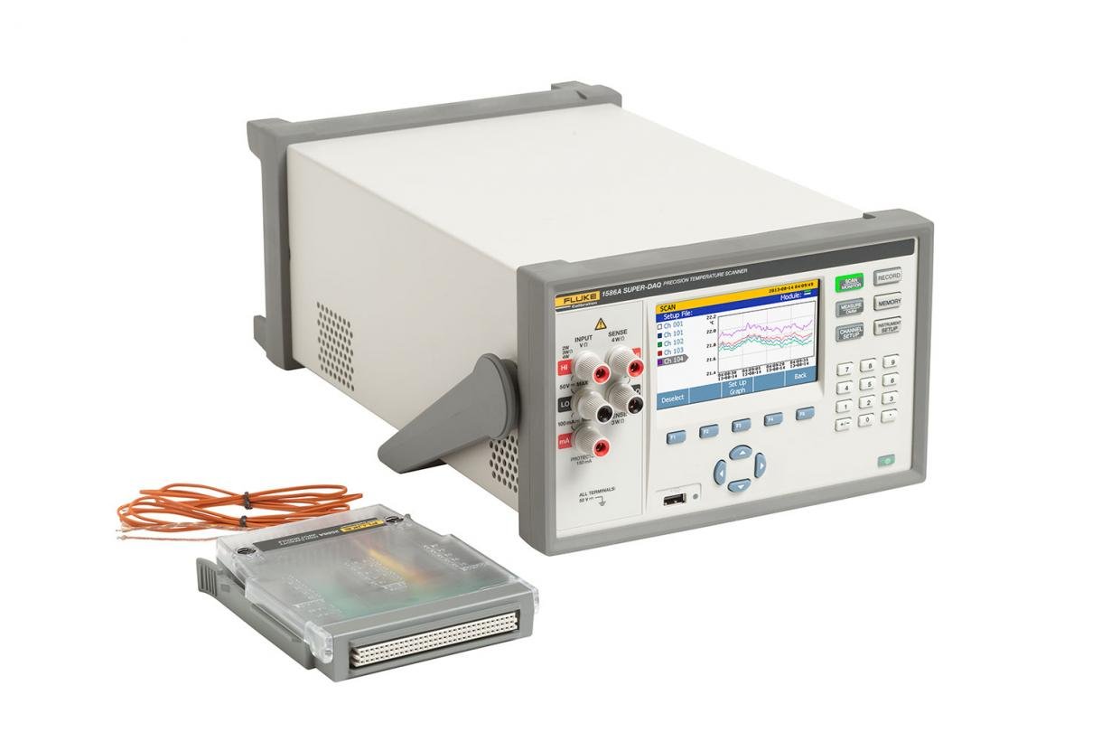


Product Overview: 1586A Highly Accurate Multi-Channel Pyrometer
1586A High Precision Multi-Channel Thermometer
Technicians, engineers, and quality management controllers use the 1586A to acquire time-stamped temperature and electrical signals and then analyze the data in detail. This is used to verify process control, analyze system interactions, and ensure compliance with regulations and quality standards. It is also used for event-related analysis in research and development and troubleshooting. Measurement data and statistics for all channels can be displayed in tabular form. Graphically, 4 channels can be plotted simultaneously in real time, making it easy to quickly check test setups and results before formal data acquisition and data analysis.
When configured with an external wiring module, the 1586A is the better benchtop pyrometer for calibrating PRTs, RTDs, thermistors, and thermocouples. When paired with a heat source such as a Fluke metering oven, thermostat bath, etc., the efficiency of sensor calibration is further improved.
The 1586A has a wide range of applications such as thermal distribution testing, temperature verification, sensor testing and calibration and many more. These applications are found in a variety of industries such as pharmaceutical, biological, food, aerospace, automotive, and more.
There are six key features that differentiate the 1586A
- Good temperature measurement accuracy
- Suitable for both industrial field and laboratory applications
- Multiple working modes
- Real-time color curve plotting
- Data transfer and data security
- Automatic sensor calibration
1. Good temperature measurement accuracy
The 1586A measures RTDs, thermocouples, and thermistors with temperature accuracy that is exceptional for its class:
- PRTs: ± 0.005 °C (with external connection module)
- Thermocouple: ± 0.5 °C (using built-in connection module)
- Thermistor: ± 0.002 °C
2. Suitable for both industrial field and laboratory applications
For field application environments, the 1586A can be configured as a built-in connection module. Connecting multiple thermocouples or RTDs to an input interface box can be a time-consuming task, especially when using many sensors for one job and needing to replace other sensors for another job. The built-in junction box allows you to connect sensors ahead of time, connecting sensors for different measurement jobs to different junction boxes, and then plugging them directly into the desired junction box as needed for the measurement. On the instrument you can directly call up the setup file directly to start testing. Depending on the need, you can measure a variety of different signals, including thermocouples, RTDs, voltages, currents or resistances on the same junction box. For laboratory applications where accuracy is more important, the 1586A can be configured with an external wiring module. The external wiring module allows connection of miniature thermocouple plugs, each with individual cold-end compensation, as well as miniature gold-plated drop-down terminals (DWF) that can be connected to bare wire, spade, and miniature banana plugs. These connections make it easy to connect and remove RTDs, thermocouples and thermistors during laboratory calibration. The external wiring module can be stacked on top of the main unit to reduce the footprint of the lab table. The 1586A's flexible industrial field and laboratory configurations reduce the amount of equipment needed and lower costs.
Multiple working modes
The 1586A can operate in four ways; you can scan, monitor, measure, or use the instrument as a digital multi-meter. Scanning is a sequential measurement of channels based on the user's channel settings. Monitoring is monitoring a channel during a scan without interrupting the scan. Measurement is the measurement of a channel without setting and recording the measurement data. The digital multi-meter mode is similar to a normal digital meter in that it quickly measures DC voltage and current, 2- or 4-wire resistance directly from the front panel without any setup.
4. Real-time color plotting
Most data acquisition systems only let you view data from one channel. Now the 1586A lets you view all channels of data in real time in a tabular format and plot curves for up to 4 channels simultaneously. You can zoom in and out of the curve scale to see details of the data or to view trends. History mode lets you scroll through the data in a scanned file...all without a computer or plotter. Curve mode and table mode can be switched between each other to provide measurement results and statistical information.
5. Data transmission and data security
The 1586A has 20MB of memory and can store up to 75,000 scans with time stamps. Data and setup files can be easily transferred to a PC via USB flash drive or LAN. The 1586A has a built-in two-stage data security mechanism to prevent unauthorized users from tampering with or altering test data or setup files. This security mechanism is important for those industries and trades that are subject to governmental controls that require reliable traceability of data.
6. Automatic sensor calibration
Utilizing the auto-test feature, sensor calibration can be accomplished without the need for a computer or software.The 1586A can be connected to a metrology oven or thermostat bath in the Fluke Metrology Calibration Department via the RS232 interface.The 1586A can control these heat sources and run the calibration steps automatically. You can set the number of temperature points to be calibrated, the temperature values, select the scanning sequence (linear, alternating, up/down), specify the reference channel, and set the desired stabilization interval.The 1586A monitors the stability of the temperature source through the reference channel, and once stabilized collects the data and then moves to the next temperature point. Once the setup is complete and activated, you can leave to do other tasks, and the 1586A can make your job easy and simple.
Product Specification: 1586A High Precision Multi-Channel Thermometer
| 1586A General Specifications | |
| Supply Voltage | 100 V setting: 90 V ~ 110 V 120 V setting: 108 V ~ 132 V 220 V setting: 198 V ~ 242 V 240 V setting: 216 V ~ 264 V |
| frequency | 47 Hz ~ 440 Hz |
| power wastage | 36 VA peak (24 W average) |
| environmental temperature | Operating: 0 °C ~ 50 °C Accuracy range: 18 °C ~ 28 °C Storage: -20 °C ~ 70 °C |
| Warm-up time. | 1 hour to meet target |
| Relative temperature (non-condensing) | Operating: 0 °C ~ 30 °C <80 %. 30 °C ~ 50 °C <50 % Storage: -20 °C ~ 70 °C <95 % |
| high degree | Work: 2,000 m Storage: 12,000 m |
| Vibration and shock | Conforms to MIL-PRF-28800F Class 3. |
| channel capacity | Total number of analog channels: 45 Voltage/resistance channels: 41 Dedicated current channels: 5 Digital I/O: 8-bit Accumulated count: 1 Alarm outputs: 6 Trigger input: 1 |
| input protection | 50 V All functions, all channels, all ranges |
| numerical channel | Number of channels: 20 Arithmetic functions: sum, difference, multiplication, division, polynomial exponent, power, square, logarithm, minimum, maximum, average, absolute value |
| trig | Internal, External (Trigger Input), Alarm, Remote (Bus), Motion, Auto Test |
| stockpile | Scan data RAM: 75,000 readings with timescale Data/setup file: 20 MB |
| USB flash drive | Interface type: Class A Function: Memory File format: FAT32 Storage Capacity: 32 GB |
| USB interface | Interface type: Class B Class: Instrument Function: Control and data transfer Control Command: SCPI |
| LAN | Function: Control and data transfer Networking: Ethernet 10/100, TCP/IP Control Command: SCPI |
| RS-232 | Connector: 9-pin (DE-9) Baud rate: 1200, 2400, 4800, 9600, 19200, 38400 Function: Temperature control |
| sizes | Height: 150 mm Width: 245 mm Depth: 385 mm Weight: 6 kg (typical configuration) Weight: 6 kg (typical) Shipping Weight: 9.5 kg (typical) |
| standards-compliant | CE, CSA, IEC 61010 3rd edition |
| Measurement indicators | |
| Unless otherwise noted, the accuracy metrics are generally applicable to medium and low speed scans, 1 hour warm-up, and temperature environments from 18°C to 28°C. The accuracy metrics are for one-year 95% confidence metrics. Accuracy metrics are one-year 95% confidence metrics. | |
| scanning speed | Fast: 10 channels/sec (0.1 sec per channel) Medium: 1 channel/sec (1 sec per channel) Slow: one channel every 4 seconds |
| Display resolution | 4 ½ ~ 6 ½ bits, depending on function and scanning speed. (Refer to Temperature Measurement Functions and Display Resolutions below) |
| PRT/RTD | |
| temperature range | -200 °C ~ 1200 °C (depending on sensor) |
| Resistance range | 0 Ω ~ 4 kΩ |
| Isolation Compensation | 0 Ω ~ 400 Ω, 4-wire: current auto-reversal 400 Ω ~ 4000 Ω or 3-wire: none |
| Excitation current commutation (0 Ω ~ 400 Ω range) | Fast: 2 ms Medium: 250 ms Slow: 250 ms |
| Maximum Lead Resistance (4-wire Ω) | 2.5 % range per line, 400 Ω and 4 kΩ |
| PRT/RTD Resistance Accuracy | ||||
| Accuracy is given in Ω or % readings, whichever is greater. Basic accuracy is given as 4-wire. When using 3-wire measurements, add 0.013Ω for channels to compensate for internal resistance mismatch and voltage misalignment. For channels x01~x20, add 0.05 Ω. If the ambient temperature is outside the specified range, multiply the temperature deviation value by the temperature coefficient and add it to the accuracy index. | ||||
| range (of scales or measuring equipment) | scanning speed | External Wiring Module and Channel 1 | built-in wiring module | Temperature exceeds 18℃~28℃ |
| 0 Ω ~ 400 Ω | slowly | 0.002 % or 0.0008 Ω | 0.003 % or 0.003 Ω | 0.0001 % or 0.0008 Ω |
| center | 0.002 % or 0.002 Ω | 0.003 % or 0.003 Ω | 0.0001 % or 0.0008 Ω | |
| plain-spoken | 0.002 % or 0.005 Ω | 0.003 % or 0.006 Ω | 0.0001 % or 0.0008 Ω | |
| 400 Ω ~ 4 kΩ | slowly | 0.004 % or 0.06 Ω | 0.006 % or 0.06 Ω | 0.0001 % or 0.008 Ω |
| center | 0.004 % or 0.1 Ω | 0.006 % or 0.1 Ω | 0.0001 % or 0.008 Ω | |
| plain-spoken | 0.004 % or 0.18 Ω | 0.006 % or 0.18 Ω | 0.0001 % or 0.008 Ω | |
| PRT/RTD Temperature Accuracy | ||||
| Accuracy is 4-wire, 100Ω rated PRT/RTD. 0.039°C is added to channel 1 to compensate for internal resistance mismatch and voltage misalignment when 3-wire measurements are used. For channels x01~x20, add 0.15℃. If the ambient temperature is outside the specified range, multiply the temperature deviation value by the temperature coefficient and add it to the accuracy indicator. Straight interpolation formulas may be used between temperature points in the table. The range of temperature measurement depends on the sensor and its characteristics. | ||||
| scanning speed | temp | External Wiring Module and Channel 1 | built-in wiring module | Temperature exceeds 18℃~28℃ |
| slowly | -200 °C | 0.002 °C | 0.008 °C | 0.002 °C |
| 0 °C | 0.005 °C | 0.008 °C | 0.003 °C | |
| 300 °C | 0.012 °C | 0.018 °C | 0.006 °C | |
| 600 °C | 0.02 °C | 0.03 °C | 0.01 °C | |
| center | -200 °C | 0.005 °C | 0.008 °C | 0.002 °C |
| 0 °C | 0.005 °C | 0.008 °C | 0.003 °C | |
| 300 °C | 0.012 °C | 0.018 °C | 0.006 °C | |
| 600 °C | 0.02 °C | 0.03 °C | 0.01 °C | |
| plain-spoken | -200 °C | 0.013 °C | 0.015 °C | 0.002 °C |
| 0 °C | 0.013 °C | 0.015 °C | 0.003 °C | |
| 300 °C | 0.014 °C | 0.018 °C | 0.006 °C | |
| 600 °C | 0.02 °C | 0.03 °C | 0.01 °C | |
| PRT/RTD Measurement Characteristics | |||
| Temperature display resolution | |||
| range (of scales or measuring equipment) | Slow / Medium | speedy | excitation voltage |
| 0 Ω ~ 400 Ω | 0.001 °C | 0.01 °C | ±1 mA |
| 400 Ω ~ 4 kΩ | 0.001 °C | 0.01 °C | 0.1 mA |
| thermistor | ||||
| temperature range | -200 °C ~ 400 °C (depending on sensor) | |||
| Resistance range | 0 Ω ~ 1 MΩ | |||
| Thermistor Accuracy | ||||
| Accuracy is given as % measured reading + Ω. Basic accuracy is based on a 4-wire, slow scan. For fast and medium speeds, increase by the number in the table. If the ambient temperature is outside the specified range, multiply the temperature deviation by the temperature coefficient and add to the accuracy index. For 2-wire measurements, channel 1 adds 0.02Ω internal resistance. For channels x01~x20, add 1.5Ω external lead resistance. | ||||
| range (of scales or measuring equipment) | slow speed | medium speed | speedy | Temperature exceeds 18℃ ~28℃ |
| 0 Ω ~ 2.2 kΩ | 0.004 % + 0.2 Ω | Add 0.3 Ω | Add 1 Ω | 0.0005 % + 0.05 Ω |
| 2.1 kΩ ~ 98 kΩ | 0.004 % + 0.5 Ω | Add 0.5 Ω | Add 1.3 Ω | 0.0005 % + 0.1 Ω |
| 95 kΩ ~ 1 MΩ | 0.015 % + 5 Ω | Add 5 Ω | Plus 13 Ω | 0.001 % + 2 Ω |
| Thermistor Temperature Accuracy | ||||
| The specifications are for 4-wire measurements. 2-wire measurements increase the specifications for internal resistance according to the table below. If the ambient temperature is out of range, the specifications are increased by 251 TP3T per degree. Specifications do not include sensor specifications. Temperature range is sensor dependent. | ||||
| 2.2 kΩ thermistor | ||||
| range (of scales or measuring equipment) | slow speed | medium speed | speedy | 2 lines |
| -40 °C | 0.001 °C | 0.001 °C | 0.01 °C | Add 0.001 °C |
| 0 °C | 0.003 °C | 0.004 °C | 0.01 °C | Add 0.004 °C |
| 25 °C | 0.006 °C | 0.011 °C | 0.02 °C | Add 0.016 °C |
| 50 °C | 0.008 °C | 0.018 °C | 0.04 °C | Add 0.05 °C |
| 100 °C | 0.047 °C | 0.114 °C | 0.28 °C | Add 0.34 °C |
| 150 °C | 0.23 °C | 0.56 °C | 1.34 °C | Add 1.7 °C |
| 5 kΩ thermistor | ||||
| range (of scales or measuring equipment) | slow speed | medium speed | speedy | 2 lines |
| -40 °C | 0.003 °C | 0.004 °C | 0.01 °C | Add 0.001 °C |
| 0 °C | 0.002 °C | 0.002 °C | 0.01 °C | Add 0.002 °C |
| 25 °C | 0.004 °C | 0.006 °C | 0.01 °C | Add 0.007 °C |
| 50 °C | 0.005 °C | 0.009 °C | 0.02 °C | Add 0.022 °C |
| 100 °C | 0.022 °C | 0.052 °C | 0.13 °C | Add 0.16 °C |
| 150 °C | 0.096 °C | 0.24 °C | 0.57 °C | Add 0.7 °C |
| 10 kΩ thermistor | ||||
| range (of scales or measuring equipment) | slow speed | medium speed | speedy | 2 lines |
| -40 °C | 0.003 °C | 0.004 °C | 0.01 °C | Add 0.001 °C |
| 0 °C | 0.002 °C | 0.002 °C | 0.01 °C | Add 0.002 °C |
| 25 °C | 0.003 °C | 0.004 °C | 0.01 °C | Add 0.004 °C |
| 50 °C | 0.005 °C | 0.009 °C | 0.02 °C | Add 0.011 °C |
| 100 °C | 0.011 °C | 0.024 °C | 0.06 °C | Add 0.067 °C |
| 150 °C | 0.04 °C | 0.098 °C | 0.24 °C | Add 0.29 °C |
| Thermistor Measurement Characteristics | |||
| Temperature display resolution | |||
| range (of scales or measuring equipment) | Slow / Medium | speedy | Source Current |
| 0 Ω ~ 2.2 kΩ | 0.0001 °C | 0.001 °C | 10 μA |
| 2.1 kΩ ~ 98 kΩ | 0.0001 °C | 0.001 °C | 10 μA |
| 95 kΩ ~ 1 MΩ | 0.0001 °C | 0.001 °C | 1 μA |
| thermocouples | ||||
| temperature range | -200 °C ~ 2315 °C (depending on sensor) | |||
| voltage range | -15 mV ~ 100 mV | |||
| Thermocouple Voltage Accuracy | ||||
| Accuracy is given as ± (% reading + µV). Basic accuracy is for medium and slow indicators. For fast indicators, increase the numbers in the table below. If the ambient temperature is outside the specified range, multiply the temperature deviation by the temperature factor and add to the accuracy indicator. | ||||
| realm | Channel 1 | Channel x01~x20 | speedy | Temperature exceeds 18℃~28℃ |
| -15 mV ~ 100 mV | 0.004 % + 4 μV | Add 2 μV | Add 1 μV | 0.0005 % + 0.0005 mV |
| Thermocouple Reference End Accuracy | ||
| module (in software) | CJC Accuracy | Temperature exceeds 18℃~28℃ |
| External Wiring Module | 0.25 °C | 0.02 °C |
| built-in wiring module | 0.6 °C | 0.05 °C |
| Thermocouple Temperature Accuracy | |||||
| Accuracy is for medium and slow indicators. Fast scanning increases the indicator by 251 TP3T. Ambient temperatures outside of the specified range increase the indicator by 121 TP3T per degree from the original indicator. external cold-end compensation (CJC) does not include compensation accuracy. Interpolation formulas may be used between temperature points in the table. Indicators do not include sensor indicators. Temperature range is sensor dependent. | |||||
| typology (Scope) |
temp | accuracy | |||
| Fixed / Internal CJC | External CJC | ||||
| Channel 1 | Channel x01~x20 | External Wiring Module | built-in wiring module | ||
| K -270 °C ~ 1372 °C |
-200 °C 0 °C 1000 °C |
0.28 °C 0.10 °C 0.14 °C |
0.41 °C 0.15 °C 0.20 °C |
0.76 °C 0.29 °C 0.32 °C |
1.60 °C 0.62 °C 0.64 °C |
| T -270 °C ~ 400 °C |
-200 °C 0 °C 200 °C 400 °C |
0.27 °C 0.10 °C 0.08 °C 0.08 °C |
0.40 °C 0.15 °C 0.12 °C 0.11 °C |
0.76 °C 0.30 °C 0.23 °C 0.20 °C |
1.60 °C 0.65 °C 0.47 °C 0.41 °C |
| R -50 °C ~ 1768 °C |
0 °C 300 °C 1200 °C 1600 °C |
0.76 °C 0.42 °C 0.33 °C 0.34 °C |
1.13 °C 0.63 °C 0.47 °C 0.49 °C |
1.16 °C 0.64 °C 0.48 °C 0.50 °C |
1.28 °C 0.71 °C 0.52 °C 0.54 °C |
| S -50 °C ~ 1768 °C |
0 °C 300 °C 1200 °C 1600 °C |
0.74 °C 0.45 °C 0.37 °C 0.39 °C |
1.11 °C 0.67 °C 0.54 °C 0.56 °C |
1.14 °C 0.68 °C 0.55 °C 0.57 °C |
1.26 °C 0.76 °C 0.60 °C 0.63 °C |
| J -210 °C ~ 1200 °C |
-200 °C 0 °C 1000 °C |
0.20 °C 0.08 °C 0.11 °C |
0.29 °C 0.12 °C 0.14 °C |
0.65 °C 0.28 °C 0.25 °C |
1.41 °C 0.61 °C 0.53 °C |
| N -270 °C ~ 1300 °C |
-200 °C 0 °C 500 °C 1000 °C |
0.42 °C 0.15 °C 0.12 °C 0.14 °C |
0.62 °C 0.23 °C 0.17 °C 0.19 °C |
0.90 °C 0.34 °C 0.24 °C 0.26 °C |
1.69 °C 0.64 °C 0.44 °C 0.45 °C |
| E -270 °C ~ 1000 °C |
-200 °C 0 °C 300 °C 700 °C |
0.17 °C 0.07 °C 0.06 °C 0.08 °C |
0.25 °C 0.10 °C 0.09 °C 0.10 °C |
0.64 °C 0.27 °C 0.21 °C 0.21 °C |
1.42 °C 0.61 °C 0.46 °C 0.45 °C |
| B 100 °C ~ 1820 °C |
300 °C 600 °C 1200 °C 1600 °C |
1.32 °C 0.68 °C 0.41 °C 0.38 °C |
1.97 °C 1.02 °C 0.60 °C 0.55 °C |
1.97 °C 1.02 °C 0.60 °C 0.55 °C |
1.97 °C 1.02 °C 0.60 °C 0.55 °C |
| C 0 °C ~ 2315 °C |
600 °C 1200 °C 2000 °C |
0.23 °C 0.28 °C 0.44 °C |
0.33 °C 0.40 °C 0.60 °C |
0.37 °C 0.45 °C 0.66 °C |
0.54 °C 0.63 °C 0.91 °C |
| D 0 °C ~ 2315 °C |
600 °C 1200 °C 2000 °C |
0.22 °C 0.26 °C 0.39 °C |
0.32 °C 0.36 °C 0.53 °C |
0.34 °C 0.39 °C 0.56 °C |
0.44 °C 0.49 °C 0.69 °C |
| G 0 °C ~ 2315 °C |
600 °C 1200 °C 2000 °C |
0.24 °C 0.22 °C 0.33 °C |
0.36 °C 0.32 °C 0.46 °C |
0.36 °C 0.32 °C 0.46 °C |
0.36 °C 0.33 °C 0.46 °C |
| L -200 °C ~ 900 °C |
-200 °C 0 °C 800 °C |
0.13 °C 0.08 °C 0.09 °C |
0.19 °C 0.12 °C 0.12 °C |
0.45 °C 0.28 °C 0.23 °C |
0.99 °C 0.62 °C 0.48 °C |
| M -50 °C ~ 1410 °C |
0 °C 500 °C 1000 °C |
0.11 °C 0.10 °C 0.10 °C |
0.16 °C 0.15 °C 0.14 °C |
0.30 °C 0.25 °C 0.21 °C |
0.64 °C 0.51 °C 0.41 °C |
| U -200 °C ~ 600 °C |
-200 °C 0 °C 400 °C |
0.25 °C 0.10 °C 0.08 °C |
0.37 °C 0.15 °C 0.11 °C |
0.71 °C 0.30 °C 0.20 °C |
1.48 °C 0.63 °C 0.40 °C |
| W 0 °C ~ 2315 °C |
600 °C 1200 °C 2000 °C |
0.24 °C 0.22 °C 0.33 °C |
0.36 °C 0.32 °C 0.46 °C |
0.36 °C 0.32 °C 0.46 °C |
0.36 °C 0.33 °C 0.46 °C |
| Thermocouple Measurement Characteristics | ||
| realm | Temperature display resolution | |
| Slow / Medium | speedy | |
| -270 °C ~ 2315 °C | 0.01 °C | 0.1 °C |
| dc voltage | ||||
| Maximum Input | Any range 50 V | |||
| Common mode rejection ratio | 140 dB @ 50 Hz or 60 Hz (1 kΩ unbalanced) ± 50 V peak max. | |||
| Differential mode rejection ratio | 55 dB @ supply frequency ± 0.1 %, ± 120 % range peak | |||
| A/D Linear | 2 ppm reading + 1 ppm range | |||
| Input logic current | 30 pA @ 25 °C | |||
| DC Voltage Accuracy | ||||
| Accuracy is given as ± (% reading + % range). Basic accuracy is an indicator for medium and slow channels. For channels x01~x20 or fast scan, refer to the indicators given in the table below. If the ambient temperature is outside the specified range, multiply the temperature deviation by the temperature coefficient and add to the original indicator. | ||||
| realm | Channel 1 | Channel x01~x20 | speedy | Temperature exceeds 18℃~28℃ |
| ±100 mV | 0.0037 % + 0.0035 % | Add 2 μ | Add 0.0008 % of range | 0.0005 % + 0.0005 % |
| ±1 V | 0.0025 % + 0.0007 % | Add 2 μ | Add 0.0008 % of range | 0.0005 % + 0.0001 % |
| ±10 V | 0.0024 % + 0.0005 % | - | Add 0.0008 % of range | 0.0005 % + 0.0001 % |
| ±50 V | 0.0038 % + 0.0012 % | - | Add 0.0008 % of range | 0.0005 % + 0.0001 % |
| DC Voltage Input Characteristics | ||||
| resolution (of a photo) | Input Impedance | |||
| range (of scales or measuring equipment) | Slow / Medium | speedy | ||
| ±100 mV | 0.1 μV | 1 μV | 10 GΩ [1] | |
| ±1 V | 1 μV | 10 μV | 10 GΩ [1] | |
| ±10 V | 10 μV | 100 μV | 10 GΩ [1] | |
| ±50 V | 100 μV | 1 mV | 10 MΩ ±1 % | |
| [1] - Inputs above ±12 V will be clamped. Clamp current to 3 mA... | ||||
| direct current | |||
| input protection | 0.15 A Auto Recovery PTC | ||
| DC Current Accuracy | |||
| Accuracy indicators are given as ± (% reading + % range). The basic accuracy is the indicator for the medium and slow channels. When using fast scanning, use the metrics given in the table below. If the ambient temperature is outside the specified range, multiply the temperature deviation by the temperature coefficient and add to the original indicator. | |||
| range (of scales or measuring equipment) | accuracy | speedy | Temperature exceeds 18℃ ~28℃ |
| ±100 μA | 0.015 % + 0.0035 % | Add 0.0008 % of range | 0.002 % + 0.001 % |
| ±1 mA | 0.015 % + 0.0011 % | Add 0.0008 % of range | 0.002 % + 0.001 % |
| ±10 mA | 0.015 % + 0.0035 % | Add 0.0008 % of range | 0.002 % + 0.001 % |
| ±100 mA | 0.015 % + 0.0035 % | Add 0.0008 % of range | 0.002 % + 0.001 % |
| DC Current Input Characteristics | |||
| resolution (of a photo) | |||
| range (of scales or measuring equipment) | Slow / Medium | speedy | Load Voltage |
| ±100 μA | 0.1 nA | 1 nA | <1 mV |
| ±1 mA | 1 nA | 10 nA | <1 mV |
| ±10 mA | 10 nA | 100 nA | <1 mV |
| ±100 mA | 100 nA | 1 μA | <1 mV |
| resistive | |||
| Maximum Lead Resistance (4-wire Ω) | 10Ω per lead for 100Ω and 1kΩ ranges, 1kΩ for all other ranges. | ||
| Resistance Accuracy | |||
| Accuracy is given as ± (% reading + % range). The basic accuracy is indicative of a 4-wire, medium/slow speed channel. For 2-wire measurements, channel 1 increases by 0.02Ω. Internal Resistors. For channels x01~x20, add 1.5Ω external lead resistor. Use the Quick Scan indicator and refer to the indicator given in the table below. If the ambient temperature is within the specified Outside the range, multiply the temperature deviation by the temperature coefficient and add it to the original indicator. |
|||
| range (of scales or measuring equipment) | accuracy | speedy | Temperature exceeds 18℃ ~28℃ |
| 100 Ω | 0.004 % + 0.0035 % | Add 0.001 % of range | 0.0001 % + 0.0005 % |
| 1 kΩ | 0.003 % + 0.001 % | Add 0.001 % of range | 0.0001 % + 0.0001 % |
| 10 kΩ | 0.004 % + 0.001 % | Add 0.001 % of range | 0.0001 % + 0.0001 % |
| 100 kΩ | 0.004 % + 0.001 % | Add 0.001 % of range | 0.0001 % + 0.0001 % |
| 1 MΩ | 0.006 % + 0.001 % | plus 0.002 % of reading plus 0.0008 % of range | 0.0005 % + 0.0002 % |
| 10 MΩ | 0.015 % + 0.001 % | plus 0.002 % of reading plus 0.0008 % of range | 0.001 % + 0.0004 % |
| 100 MΩ | 0.8 % + 0.01 % | Add 0.01 % of range | 0.05 % + 0.002 % |
| Resistive Input Characteristics | |||
| range (of scales or measuring equipment) | Slow / Medium | speedy | Excitation current (open circuit voltage) |
| 100 Ω | 0.1 mΩ | 1 mΩ | 1 mA (4 V) |
| 1 kΩ | 1 mΩ | 10 mΩ | 1 mA (4 V) |
| 10 kΩ | 10 mΩ | 100 mΩ | 100 μA (6 V) |
| 100 kΩ | 100 mΩ | 1 Ω | 100 μA (12 V) |
| 1 MΩ | 1 Ω | 10 Ω | 10 μA (12 V) |
| 10 MΩ | 10 Ω | 100 Ω | 1 μA (12 V) |
| 100 MΩ | 100 Ω | 1 kΩ | 0.1 μA (12 V) |
| Digital I/O | |
| Absolute Voltage Range | -4 V ~ 30 V |
| Input Minimum Logic High | 2.0 V |
| Input Maximum Logic Low | 0.7 V |
| Output Type | open drain active low |
| Output Logic Low (<1 mA) | 0 V ~ 0.7 V |
| Maximum Sink Current | 50 mA |
| Output Resistance | 47 Ω |
| ~talizer | |
| Absolute Voltage Range | -4 V ~ 30 V |
| Minimum Logic High | 2.0 V |
| Maximum Logic Low | 0.7 V |
| Minimum Pulse Width | 50 μs |
| Maximum Frequency | 10 kHz |
| Debounce Time | 1.7 ms |
| Maximum Count | 1048575 (20 bits) |
| Trigger | |
| Absolute Voltage Range | -4 V ~ 30 V |
| Minimum Logic High | 2.0 V |
| Maximum Logic Low | 0.7 V |
| Minimum Pulse Width | 50 μs |
| Maximum Latency | 100 ms |
| Alarm Output | |
| Absolute Voltage Range | -4 V ~ 30 V |
| Output Type | open drain active low |
| Output Logic Low (<1 mA) | 0 V ~ 0.7 V |
| Maximum Sink Current | 50 mA |
| Output Resistance | 47 Ω |
| 1586-2588 External Wiring Module Indicator | |
| Maximum Input | 50 V |
| lossy voltage | <2 μV |
| 3 wire internal resistance mismatch | <50 mΩ |
| Basic CJC Accuracy | 0.25 °C |
| 1586-2586 Built-in Wiring Module Indicator | |
| Maximum Input | 50 V |
| lossy voltage | <2 μV |
| 3 wire internal resistance mismatch | <50 mΩ |
| Basic CJC Accuracy | 0.6 °C |
Model: 1586A High Precision Multi-Channel Thermometer
1586A/1DS
Mainframe with one external wiring module (20 channels)
1586A/1DS/C
Super-DAQ Precision Temperature Scanner, 1 DAQ-STAQ Multiplexer, Accredited Calibration
1586A/2DS
Mainframe with two external wiring modules (40 channels)
1586A/2DS/C
Super-DAQ Precision Temperature Scanner, 2 DAQ-STAQ Multiplexers, Accredited Calibration
1586A/DS-HC
The main unit is equipped with an internal wiring module and an external wiring module.
1586A/DSHC/C
Super-DAQ Precision Temperature Scanner, 1 High-Capacity Module, 1 DAQ-STAQ Multiplexer, Accredited Calibration
1586A/1HC
Mainframe with one built-in wiring module (20 channels)
1586A/1HC/C
Super-DAQ Precision Temperature Scanner, 1 HIgh-Capacity Module, Accredited Calibration
1586A/2HC
Mainframe with two built-in wiring modules (40 channels)
1586A/2HC/C
Super-DAQ Precision Temperature Scanner, 2 High-Capacity Modules, Accredited Calibration
2680A-APSW v6.0
Fluke DAQ 6.0 Application Software for Fluke data acquisition products.
TQSOFT-IQ/OQ
TQSoft Pharma Process Analysis and Validation Software
TQAERO
TQAero Furnace Validation Software
VAL-BNDR-TQS
Validation Reference Binder


