 Comprehensive test and measurement service provider-Shenzhen Weike Electronic Technology Co.
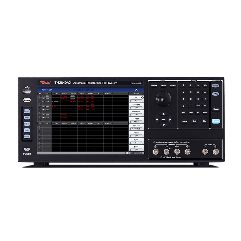
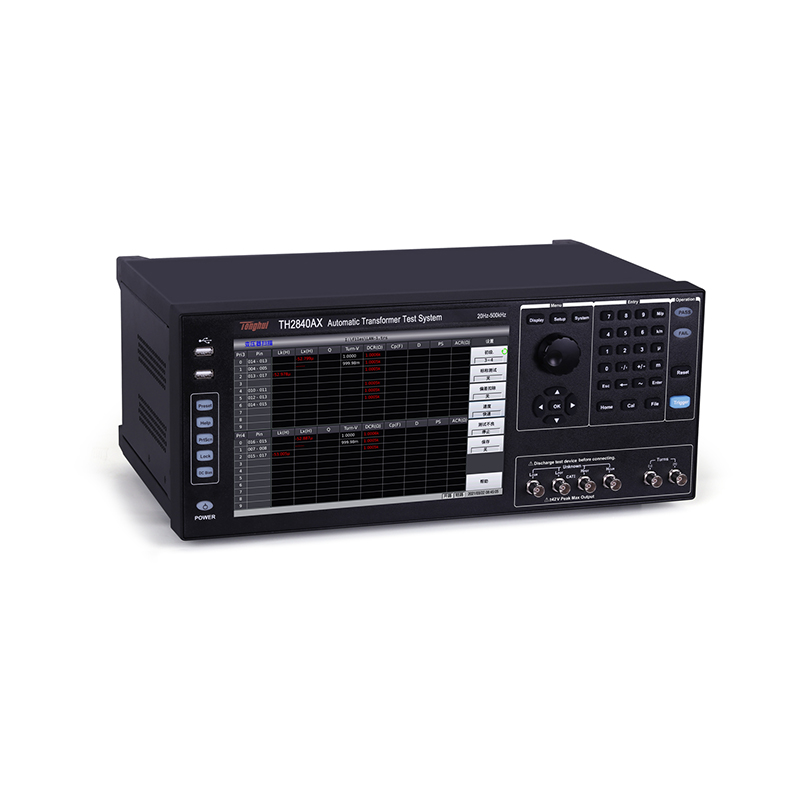
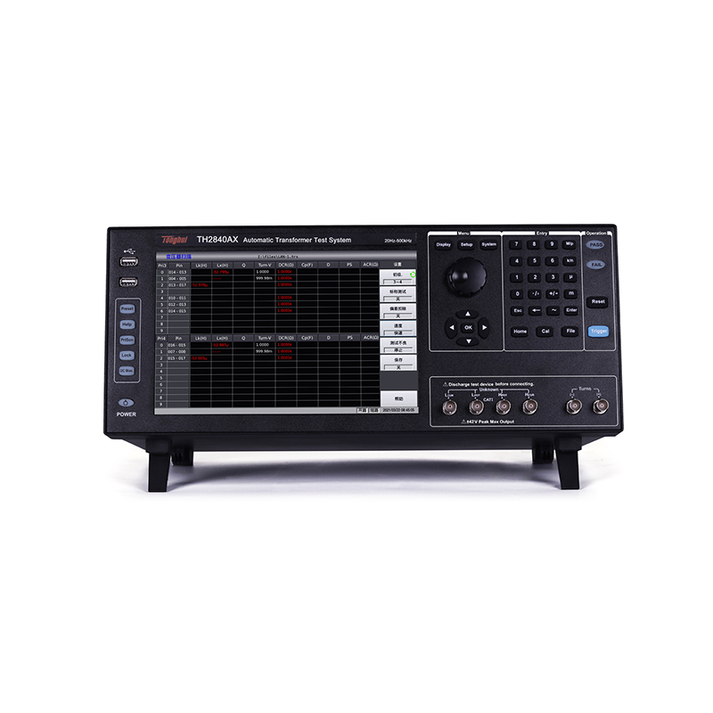


TH2840X series automatic transformer test system is Changzhou Tonghui Electronics in many years of experience in transformer testing, the use of a new generation of technology to succeed in a new generation of automatic transformer test system, innovative use of dual-CPU architecture, the underlying system of Linux, 10.1-inch capacitive touch screen, Chinese and English operating interface, built-in instructions and help and other new generation of technology, to solve the previous test The system setup is cumbersome, the test speed is slow, the display is complementary, the PIN foot position is insufficient and other defects.
TH2840X series automatic transformer test system benefits from the use of a 10.1-inch, resolution up to 1280 * 800 capacitive touch screen, you can set all the feet, test conditions, feet in series and parallel, balance settings, etc., the same screen operation, to simplify the setup process, and reduces the difficulty of the instrument operator to set up.
A. Revolutionary design
Dual-CPU architecture, Linux underlying, support for touch screen, keyboard, mouse, built-in Chinese and English help and other design, bringing an unparalleled operating experience, the
Significantly reduces the barrier to entry for operators and improves testing efficiency several times over.
The following is a comparison between the classic TH2829X and the latest model.
| sports event | TH2840X | TH2829X |
| test speed | Fast 21ms (100Hz), 50 cycles/sec (x8x)
Fast 3ms (1kHz), 300 cycles/sec (x5x) Fast 3ms (10kHz), 300 cycles/sec (x1.5x) Fast +2ms (>=2kHz), 500 cycles/sec (x2.5x) |
Fast +150ms (100Hz), 6.6 times/second
Fast +15ms (1kHz), 66 times/second Fast +5ms (10kHz), 200 cycles/sec. |
| Test Frequency | ----
500kHz 2MHz |
200kHz
500kHz 1MHz |
| test level | AC20V(20Hz~1MHz)
AC15V(1MHz~2MHz) |
AC10V |
| Built-in DC bias | Bias voltage ±40V | Bias voltage ±10V |
| Built-in bias current source | 2A (standard), 10V supply voltage | 2A (optional), 8V supply voltage |
| Support for scanning feet
|
24PIN (TH1831 scanner box)
48X6PIN (up to 288PIN) Host Universal |
20PIN
48PIN NX (up to 192PIN) |
| USB HOST interface | 2 pcs, support mouse, keyboard | 1 |
| system architecture | Dual-CPU solution to save display time | single CPU |
| embedded system | Linux system
Perfectly supports all kinds of USB flash drives Support Network Support mouse, keyboard operation, support capacitive touch screen |
unsystematic |
| monitor (computer) | 10.1-inch capacitive touchscreen 1280 x 800 display for more information | 7-inch TFT display |
| Range switching | Electronic switch, fast speed, long life, no noise | Relay, slow, short life span |
| Number of documents | 400 (288PIN) | 20 (NX192PIN) |
| hand | Electronic instruction manual, view brief description directly on the instrument | not have |
B.10.1-inch large screen, simplify the setup efficiency, reduce the operation difficulty
10.1-inch touch screen, 1280 * 800 resolution, touch the large screen to bring more benefits is that all the transformer feet associated with the test parameters, feet in series and parallel, sorting parameters and other parameters placed on the same screen, directly with the hand or keyboard and mouse operation, not only fast operation and looks like by no means crowded and cluttered.
According to the cultivation of Tonghui Electronics in the field of transformer test for more than ten years, it has been continuously improving for the problems encountered in the test of the early automatic transformer comprehensive test system.
1. Graphical transformer foot position association page
Early automatic transformer test system foot associated with the page setup is cumbersome, and can not be the first time the transformer foot, test fixture foot one-to-one correspondence, setup difficulties

For this drawback, a new generation of automatic transformer test system in the foot associated interface increased picture, color, frame line and other elements to enhance the foot set up and test the correlation of the bullhorn, the user can be the first time the transformer foot associated with the physical object, reduce the difficulty of setting and wiring errors possible!

2. Single page setup transformer test conditions
Early automatic transformer test systems need to enter different setting pages to set test parameters, such as setting Lx parameters, need to enter 6-7 different sub-pages, quite cumbersome.

After improvement, now multiple parameters can be switched in one page, and all the related parameters of Lx can be set up in one table, which is clear at a glance and greatly improves the setting efficiency.

3. Improvement of serial and parallel setting of the foot position
When setting the footer for earlier models, you need to go to different sub-pages for serial and parallel footers.

Improved to set up the footer series and parallel connections directly in one page.

4. Improved multi-foot input method
In transformer scanning settings, it is often necessary to enter a number of consecutive foot inputs such as 1,2,3,4,5,6, so the input method has been improved to use the customary way of inputs such as 1~6 to indicate the consecutive way of inputs, which simplifies the display page and improves the efficiency of inputs.


5. Increase the average number of times and delay settings for each scanning parameter to increase stability.
In the transformer scanning test, due to some of the inductance circuit inductance is large, need to be stabilized after a certain period of time to read the accurate value, for this situation, each scanning parameter to increase the average number of times and delay settings to increase the stability, and at the same time will not affect the speed of the other parameters of the test.

6. Improve the leakage sense setting method
When testing leakage inductance Lk in multiple windings, earlier instruments needed to constantly switch between corresponding windings and set the nominal value and limit value, which was very troublesome. The new generation of automatic transformer test system improves this setup by setting the foot position and connection mode of different secondary windings directly in the same setup page, eliminating the need to input the leakage inductance pins, and inputting the nominal value, upper and lower limits directly at the corresponding pins.

7. Improved balanced scanning method
When testing the balance of multi-winding transformers, just like testing leakage inductance, earlier instruments needed to constantly switch the secondary balance foot position and set the corresponding limit value, the new generation of automatic transformer test system has improved this setting, all the balance setting items can be set up in the same page, and in response to the shortcomings of the earlier balancing points of up to 5 points, it has been upgraded to 10 points.

C.LCR measurement function
1. This function is optional
2. Please refer to TH2840 series LCR digital bridge technical parameters for detailed functions and indicators.
| Product Model | TH2840AX | TH2840BX | TH2840NX | |
|
demonstrate |
monitor (computer) | 10.1-inch (diagonal) capacitive touch screen | ||
| proportions | 16:9 | |||
| resolution (of a photo) | 1280×RGB×800 | |||
|
Test Frequency |
realm | 20Hz-500kHz | 20Hz-2MHz | 20Hz-500kHz |
| accurate | 0.01% | |||
|
resolution (of a photo) |
0.1mHz (20.0000Hz-99.9999Hz) | |||
| 1mHz (100.000Hz-999.999Hz) | ||||
| 10mHz (1.00000kHz-9.99999kHz) | ||||
| 100mHz (10.0000kHz-99.9999kHz) | ||||
| 1Hz (100.000kHz-999.999kHz ) | ||||
| 10Hz (1.00000MHz-2.00000MHz) | ||||
|
AC Test Signal Mode |
Rated value (ALCOFF) | The set voltage is the Hcur voltage when the test terminal is open circuit | ||
| The set current is the current from Hcur when the test terminal is short-circuited. | ||||
| constant value
(ALCON) |
Keep the voltage on the DUT the same as the set value | |||
| Keep the current on the DUT the same as the set value | ||||
|
test level |
voltage range | 5mVrms-20Vrms | F≤1MHz 5mVrms-20Vrms
F>1MHz 5mVrms-15Vrms |
5mVrms-20Vrms |
| accuracy | ± (10% x setpoint + 2mV) (AC ≤ 2Vrms)
± (10% x setpoint + 5mV) (AC > 2Vrms) |
|||
|
resolution (of a photo) |
1mVrms (5mVrms-0.2Vrms) | |||
| 1mVrms (0.2Vrms-0.5Vrms) | ||||
| 1mVrms(0.5Vrms-1Vrms) | ||||
| 10mVrms (1Vrms-2Vrms) | ||||
| 10mVrms (2Vrms-5Vrms) | ||||
| 10mVrms (5Vrms-10Vrms) | ||||
| 10mVrms(10Vrms-20Vrms) | ||||
| current range | 50μArms-100mArms | |||
|
Resolution (100Ω internal resistance) |
10μArms(50μArms-2mArms) | |||
| 10μArms(2mArms-5mArms) | ||||
| 10μArms(5mArms-10mArms) | ||||
| 100μArms (10mArms-20mArms) | ||||
| 100μArms (20mArms-50mArms) | ||||
| 100μArms (50mArms-100mArms) | ||||
|
RDC Testing |
voltage range | 100mV-20V | ||
| resolution (of a photo) | 1mV(0V-1V) | |||
| 10mV(1V-20V) | ||||
| current range | 0mA-100mA | |||
| resolution (of a photo) | 10μA(0mA-10mA) | |||
| 100μA (10mA-100mA) | ||||
|
DC Bias |
voltage range | 0V-±40V | ||
| accuracy | AC≤2V 1%×set voltage+5mV | |||
| AC>2V 2% x set voltage +8mV | ||||
| resolution (of a photo) | 1mV (0V - ±1V) | |||
| 10mV (±1V - ±40V) | ||||
| current range | 0mA-±100mA | |||
| resolution (of a photo) | 10μA (0mA-10mA) | |||
| 100μA (10mA-100mA) | ||||
|
Built-in current source |
current range | 0mA-2A | ||
| accuracy | I>5mA ± (2% x setpoint + 2mA) | |||
| resolution (of a photo) | 1mA | |||
| Output Impedance | 30Ω, ±4 @1kHz | |||
| 100Ω, ±2 @1kHz | ||||
| LCR Module Measurement Parameters | ||||
|
measured parameter |
way (of life) | Four parameters can be selected arbitrarily | ||
| AC | Cp/Cs, Lp/Ls, Rp/Rs, |Z|, |Y|, R, X, G, B, θ, D, Q, VAC, IAC | |||
| DC | RDC, VDC, IDC | |||
| Test Side Configuration | four-pronged attack (e.g. marriage) | |||
| Test cable length | 0m, 1m, 2m, 4m | |||
| mathematical operation | Absolute deviation from nominal value Δ, percentage deviation from nominal value Δ% | |||
| equivalence mode | Series, parallel | |||
| calibration function | Open OPEN, Short SHORT, Load LOAD | |||
| Measured average | 1-255 times | |||
| Range Selection | Auto AUTO, Manual HOLD | |||
| Range Configuration | LCR | 100mΩ, 1Ω, 10Ω, 20Ω, 50Ω, 100Ω, 200Ω, 500Ω, 1kΩ, 2kΩ, 5kΩ, 10kΩ, 20kΩ, 50kΩ, 100kΩ | ||
| RDC | 1Ω, 10Ω, 20Ω, 50Ω, 100Ω, 200Ω, 500Ω, 1kΩ, 2kΩ, 5kΩ, 10kΩ, 20kΩ, 50kΩ, 100kΩ | |||
|
Measurement time (ms) |
Fast+: 0.56ms
Fast: 3.3ms Medium speed: 90ms Slow: 220ms |
|||
| Maximum accuracy | 0.05% (refer to specifications) | |||
| Measurement display range | ||||
| Cs, Cp | 0.00001pF-9.99999F | |||
| Ls, Lp | 0.00001μH-99.9999kH | |||
| D | 0.00001-9.99999 | |||
| Q | 0.00001-99999.9 | |||
| r, rs, rp, x, z, rdc | 0.001mΩ-99.9999MΩ | |||
| G, B, Y | 0.00001μs-99.9999S | |||
| VDC | ±0V-±999.999V | |||
| IDC | ±0A-±999.999A | |||
| θr | -3.14159-3.14159 | |||
| θd | -179.999°-179.999° | |||
| Δ% | ± (0.000%-999.9%) | |||
| TurnsRatio | 1:0.001-1000:1 | |||
| For other test parameters of LCR module, please refer to TH2840 series LCR digital bridge technical parameters section. | ||||
| Transformer Measurement | ||||
|
test parameter |
Cs/Cp: Capacitance, Ls/Lp: Inductance, DCR: DC Resistance, Zx: Impedance, Rs/Rp: Resistance, D: Loss, Q: Quality Factor, dZ: Phase Angle, Lk: Leakage Inductance, Phase: Phase), Balance: Balance
Turns-Ratio: Ns:Np=U2/U1, Np:Ns=U1/U2 Turns (number of turns): Ns=Np×U2/U1, Np=Ns×U1/U2 |
|||
| test pattern | progression | In the single trigger mode, manually triggered once, measured all the test parameters of the transformer set once. | ||
| one-step | In the single-trigger mode, manually trigger once to measure a measurement parameter of the transformer, and trigger again to measure the next parameter. | |||
|
Measurement time (ms) |
speedy | Fast: 3.3ms, Fast+: 1ms (>10kHz) | ||
| medium speed | Medium speed: 90ms | |||
| slow speed | Slow: 220ms | |||
| bias source | Reference bias section parameters | |||
| Average number of times | Each test parameter can be set to a different average number of times, the average number of times for 0-255 | |||
| latency | Different delay times can be set for each test parameter. | |||
| Transformer Scanning | ||||
| Built-in scanning channels (PIN) | 6 x (24 x 2) = 288PIN (AX,BX without built-in scanner board) | |||
| Transformer HANDLE interface | Pin Definitions | NS1-NS30, GOOD, NG, TEST, Trigger, Reset (Consistent with TH2829X series) (NX) (AX,BX NSI-NS9) | ||
| Output Characteristics | Optocoupler Isolated, ULN2003 Driver Enhanced, Collector Outputs | |||
| paradigm | Direct reading, percentage | |||
| range (of scales or measuring equipment) | Automatic, Hold | |||
| bias source | Reference bias section parameters | |||
| External Scanner Box | Compatible with TH1901 series, TH1831 scanner box | |||
| Number of windings | junior ranking | 60 | ||
| secondary | 9 | |||
| Average number of times | Each test parameter can be set to a different average number of times, the average number of times for 0-255 | |||
| latency | Different delay times can be set for each test parameter | |||
|
Measurement time (ms) |
speedy | Fast: 3.3ms (≥1kHz), Fast+: 1ms (≥10kHz) (excluding relay action time) | ||
| medium speed | Medium speed: 90ms | |||
| slow speed | Slow: 220ms | |||
| Test Lead Interface | 25*2pin FRC socket, pinout identical to TH2829 series (NX) | |||
| Other features and parameters | ||||
| store a call (computing) | inside (part, section) | Approx. 100M non-volatile memory test setup file | ||
| External USB | Test setup files, screenshot graphics, log files | |||
| Keyboard Lock | Lockable front panel keys | |||
|
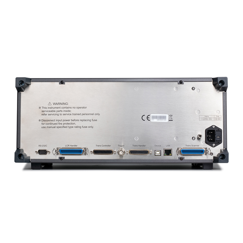
connector |
USB HOST | 2 USB HOST ports, can be connected to the mouse, keyboard, U disk at the same time can only use a | ||
| USB DEVICE | Universal Serial Bus socket, small Class B (4 contact positions); USBTMC-USB488 and USB2.0 compliant, female connector for connection to external controllers. | |||
| LAN | 10/100BaseT Ethernet, 8-Pin, Speed Adaptive | |||
| HANDLER | For Bin Staging Signal Output | |||
| External DC BIAS
containment |
Supports TH1778A (transformer scanning is not supported) | |||
| RS232C | Standard 9-pin, Crossed | |||
| RS485 | Can receive conversion or external RS232 to RS485 module | |||
| Power-on warm-up time | 60 minutes. | |||
| Input Voltage | 100-120VAC/198-242VAC selectable, 47-63Hz | |||
| power wastage | Not less than 130VA | |||
| Dimensions (WxHxD) mm3 | 430mm(W)x177mm(H)x265mm(D) | 430mm(W)x177mm(H)x405mm(D) | ||
| Weight (kg) | 11kg | 17kg | ||
■ Test speeds up to 0.56ms (1800 cycles/sec) (>10kHz) without relay action time
■ Test levels up to 20Vrms
■ Bias voltage is built-in ±40V/±100mA/2A
■ Up to 288 Pin Test Positions (TH2840NX only)
■ Industry-friendly user experience: Linux underpinnings, built-in help files
■ 10.1-inch 1280 x 800 capacitive touch screen
■ Graphical foot association setup page makes wiring less of a challenge
■ Lk setting is more intuitive without inputting leakage inductance pins.
■ Enhanced balance scanning from 5 to 10 points
■ range switching using electronic switches, fast, long life, no noise
■ Optional LCR function
■ About 100M setting file saving space in the machine, and a large amount of U disk setting file saving capacity.
■ Provide host computer support for early model file format conversion to ensure compatibility
■ Switching transformer scanning test, comprehensive characterization
■ Network transformer scanning tests, comprehensive characterization
■ Multi-scan testing of discrete passive components (inductors L, resistors R, capacitors C)
■ Multi-scan testing of relay driver packages, contact contact resistance
■ Multiple DC resistance DCR scan test
■ Comprehensive test analysis of multiple passive components in impedance networks
| standard equipment | |||||
| Accessory Name | model number | ||||
| Boxed Four-Ended Insulated Locking Kelvin Test Leads | TH26011BS | ||||
| Scanner Connection Cable | TH26058A | ||||
| Test Leads at Both Ends | TH26004B | ||||
| Manual Transformer Scanning Test Fixture | TH1806B | ||||
| Foot-activated switch | TH1801-001 | ||||
Recommended


