 Comprehensive test and measurement service provider-Shenzhen Weike Electronic Technology Co.
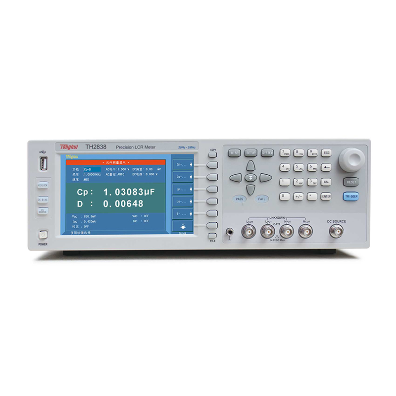

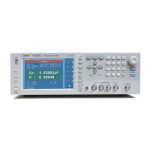

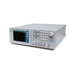


TH2838/TH2838H/TH2838A is a new generation of impedance tester successfully developed by adopting the current international advanced auto-balance bridge principle, with the basic accuracy of 0.05%, the fastest test speed up to 5.6ms, the frequency range of 20Hz-2MHz and the impedance test range of up to 1GΩ, it can satisfy the requirements of component and material measurements, and it is especially It is especially useful for low loss (D) capacitors and high quality factor (Q) inductors. The four-terminal port configuration effectively eliminates the influence of electromagnetic coupling of the test line, and extends the lower limit of low-impedance testing capability downward by a factor of ten compared to conventional five-terminal configurations.
The TH2838/TH2838H/TH2838A supports high power test conditions with 20V AC test signal and 40V DC bias, and the enhanced multi-parameter list scanning/multi-parameter graphical analysis capability will help users to expand their ability to fully evaluate components.
TH2838/TH2838H/TH2838A is a powerful tool for electronic component design, inspection, quality control and production testing. Its excellent performance and functionality provide a powerful tool for circuit design and development as well as research and development of materials (electronic and non-electronic).
The TH2838/TH2838H/TH2838A with its performance can realize various tests such as IEC and MIL standards.

Functional Features
- highly accurate
The auto-balanced bridge ensures higher frequency accuracy over a wider frequency range than ordinary LCR bridges! The following figure compares the accuracy difference between auto-balanced bridges and ordinary bridges in the frequency range of 0-10MHz, using Tonghui bridges as an example. Currently, Tonghui's auto-balanced bridges include TH2839 series, TH2838 series and TH2828 series.

- High stability and consistency

- high speed

- Functions and Interfaces


- Material Dielectric Constant Testing
TH2838 series with the special material test fixture TH26077 and the host computer software can easily and accurately measure the dielectric constant of materials at different frequencies.

- Optional accessories


- host computer software
- a) Generic host computer software
Test approach:

File Save:

Hardware connection: RS232C, USB, GPIB, LAN
Data image saving format: TXT, XLS, MDB, CSV, BMP, JPG, PNG
Other functions: automatic recording, setting file saving, user management, etc.
- b) Piezoelectric ceramics host computer software
Analyze the settings:

Analyze the results:

- c) Impedance analysis software (equivalent circuit analysis software)
Different types of devices in real life can be equated into simple circuit models consisting of 3-4 devices. The Impedance Analyzer host computer provides 7 basic circuit models for the equivalence of these devices. The software also provides an auto-matching function, i.e., if the device under test is a black box, the software automatically matches the model that best matches it and calculates the parameters. You can compare the impedance fitting curves of the simulated equivalent circuit parameter values with the actual measured impedance curves, and you can also fit the model of your choice according to the parameters you input. The equivalent circuit model can be directly exported to a TXT file for users to save and use.

| Product Model | TH2838 | TH2838H | TH2838A | ||||||
| Test Signal Source | |||||||||
| Signal source output impedance | 100Ω, ±1% @1kHz | ||||||||
| Test Frequency | realm | 20Hz-2MHz | 20Hz - 1MHz | ||||||
| Setup Step | 20.0000Hz - 99.9999Hz | 1mHz | |||||||
| 100.000Hz - 999.999Hz | 10mHz | ||||||||
| 1.00000kHz - 9.99999kHz | 100mHz | ||||||||
| 10.0000kHz - 99.9999kHz | 1Hz | ||||||||
| 100.000kHz - 999.999kHz | 10Hz | ||||||||
| 1.00000MHz - 2.00000MHz | 100Hz | ||||||||
| AC Test Signal Mode | Rated value (ALC OFF): Set voltage is the Hcur voltage when the test terminal is open circuit Set current is the current from Hcur when the test terminal is short-circuited Constant value (ALC ON): Keep the voltage on the DUT the same as the set value Keep the current on the DUT the same as the set value | ||||||||
| A C signal | voltage range | 5mVrms - 2Vrms | F≤1MHz 5mVrms- 20Vrms
F >1MHz 5mVrms - 15Vrms |
5mVrms - 2Vrms | |||||
| resolution (of a photo) | 5mVrms - 0.2Vrms | 100µVrms | |||||||
| 0.2Vrms - 0.5Vrms | 200µVrms | ||||||||
| 0.5Vrms - 1Vrms | 500µVrms | ||||||||
| 1Vrms - 2Vrms | 1mVrms | ||||||||
| 2Vrms - 5Vrms | 2mVrms | ||||||||
| 5Vrms - 10Vrms | 5mVrms | ||||||||
| 10Vrms - 20Vrms | 10mVrms | ||||||||
| current range | 50µArms - 20mArms | 50µArms -100mArms | 50µArms - 20mArms | ||||||
| resolution (of a photo) | 50µArms - 2mArms | 1µArms | |||||||
| 2mArms - 5mArms | 2µArms | ||||||||
| 5mArms - 10mArms | 5µArms | ||||||||
| 10mArms - 20mArms | 10µArms | ||||||||
| 20mArms - 50mArms | 20µArms | ||||||||
| 50mArms-100mArms | 50µArms | ||||||||
| Rdc Testing | voltage range | 100mV - 2V | |||||||
| resolution (of a photo) | 100µV | ||||||||
| current range | 0mA- 20mA | ||||||||
| resolution (of a photo) | 1µA | ||||||||
| D C bias | voltage range | 0V - ±10V | 0V - ±40V | 0V - ±10V | |||||
| resolution (of a photo) | 0V - 5V | 100µV | |||||||
| 5V - 10V | 1mV | ||||||||
| 10V - 20V | 2mV | ||||||||
| 20V - 40V | 5mV | ||||||||
| current range | 0mA- ± 100mA | ||||||||
| resolution (of a photo) | 0 A - 50mA | 1µA | |||||||
| 50mA - 100mA | 10µA | ||||||||
| voltage source | voltage range | ------ | -10V - 10V | ------ | |||||
| resolution (of a photo) | ------ | 1mV | ------ | ||||||
| current range | ------ | -45mA - +45mA | ------ | ||||||
| Output Impedance | ------ | 100Ω | ------ | ||||||
| monitor (computer) | |||||||||
| Size/Type | 7-inch (diagonal) TFT LCD monitor | ||||||||
| proportions | 16:9 | ||||||||
| resolution (of a photo) | 800×RGB×480 | ||||||||
| measurement function | |||||||||
| readings | 6-digit readout resolution | ||||||||
| test parameter | Cp-D, Cp-Q, Cp-G, Cp-Rp, Cs-D, Cs-Q, Cs-Rs, Lp-D, Lp-Q, Lp-G, Lp-Rp, Lp-Rdc, Ls-D, Ls-Q, Ls-Rs, L s-RDCRDC, R-X, Z -θd, Z -θr, G-B, Y -θd, Y -θr, VAC-IACVDC-IDC | ||||||||
| math function | A(X+B)+C, X is the test parameter, A, B, C are the input parameters | ||||||||
| equivalent circuit | Series, parallel | ||||||||
| bias measurement | Absolute deviation from nominal value Δ, percentage deviation from nominal value Δ% | ||||||||
| calibration function | Open OPEN, Short SHORT, Load LOAD | ||||||||
| Range Selection | Auto AUTO, Manual HOLD | ||||||||
| range (of scales or measuring equipment) | LCR | 100mΩ, 1Ω, 10Ω, 20Ω, 50Ω, 100Ω, 200Ω, 500Ω, 1kΩ, 2kΩ, 5kΩ, 10kΩ, 20kΩ, 50kΩ, 100kΩ, total 15 steps | |||||||
| Rdc | 1Ω, 10Ω, 20Ω, 50Ω, 100Ω, 200Ω, 500Ω, 1kΩ, 2kΩ, 5kΩ, 10kΩ, 20kΩ, 50kΩ, 100kΩ, total 15 steps | ||||||||
| Trigger Mode | INT, MAN, EXT, BUS | ||||||||
| Trigger delay | 0s - 999s with 100μs resolution | ||||||||
| Test Side Configuration | four-pronged attack (e.g. marriage) | ||||||||
| Test cable length | 0m, 1m, 2m, 4m | ||||||||
| Measured average | 1-255 times | ||||||||
| Measuring time (ms) | Speed Mode | 20Hz | 100Hz | 1kHz | 10kHz | 100kHz | 1MHz | 2MHz | |
| FAST | 330 | 100 | 20 | 7.7 | 5.7 | 5.6 | 5.6 | ||
| MED | 380 | 180 | 110 | 92 | 89 | 88 | 88 | ||
| LONG | 480 | 300 | 240 | 230 | 220 | 220 | 220 | ||
| Measurement display range a 1 x 10-18E 1 x 10¹⁸ | |||||||||
| Cs, Cp | ±1.00000 aF - 999.999 EF | ||||||||
| Ls,Lp | ±1.00000 aH - 999.999 EH | ||||||||
| D | ±0.00001 - 9.99999 | ||||||||
| Q | ±0.01 - 9999.99 | ||||||||
| R, Rs, Rp, X, Z, Rdc | ±1.00000 aΩ - 999.999 EΩ | ||||||||
| G,B,Y | ±1. 00000 aS - 999.999 ES | ||||||||
| Vdc | ±1.00000 aV - 999.999 EV | ||||||||
| Idc | ±1.00000 aA - 999.999 EA | ||||||||
| θ r | ±1.00000 rad - 3.14159 rad | ||||||||
| θ d | ±0.0001 deg - 180.000 deg | ||||||||
| Δ% | ±0.0001% - 999.999% | ||||||||
| Basic Measurement Accuracy | 0.05% (see instructions for details) | ||||||||
| List Scanning | |||||||||
| Scanning Points | Up to 201 points | ||||||||
| Multi-parameter scanning | Each scanning point can be arbitrarily set function (main and sub parameters), frequency, AC level, DC bias (voltage or current), speed and other general test parameters; each scanning point supports open circuit, short circuit, load calibration; scanning results list can be arbitrarily selected to display the desired parameters. | ||||||||
| Trigger Mode | Sequential SEQ | When triggered once, measurements are taken at all scan points. /EOM/INDEX is output only once. | |||||||
| Step STEP | Performs one scan point measurement per trigger. Each point outputs /EOM/INDEX, but the list scan comparator result is only output at the last /EOM. | ||||||||
| List Scan Comparator | A pair of lower and upper limits can be set for each scan point. Selectable: judged by the first scan parameter / judged by the second parameter / not used for each limit. | ||||||||
| Graphic Scan Analysis | |||||||||
| Scanning Points | Points 51, 101, 201, 401, 801 are optional | ------ | |||||||
| scanning track | Primary/sub-parameters selectable | ------ | |||||||
| Display range | Automatic, Locked | ------ | |||||||
| Logarithmic, linear | ------ | ||||||||
| scanning parameter | Frequency, ACV, ACI, DCV BIAS/DCI BIAS, DC Voltage Source | ------ | |||||||
| Scan result display | Maximum/minimum value of main/sub-parameter, setpoint main/sub-parameter value | ------ | |||||||
| Scanning Graphics Storage | Scanning graphics can be stored, external USB memory or data uploaded to a host computer. | ------ | |||||||
| comparator | |||||||||
| B i n classification | main parameter | 9 BIN, OUT_OF_BINS, AUX_BIN and LOW_C_REJECT | |||||||
| parameterization | HIGH, IN, LOW | ||||||||
| Bin Limit Setting | Absolute value, deviation value, percent deviation value | ||||||||
| Bin Count | 0 -- 999999 | ||||||||
| PASS/FAIL indication | If the main parameter is one of the 9 BINs and the sub parameter is IN, the front panel PASS lamp is ON, otherwise FAIL ON. | ||||||||
| Measurement Auxiliary Functions | |||||||||
| Data buffer storage function | 201 measurements can be read in batches | ||||||||
| Save/Recall Functions | 40 sets of instrument internal non-volatile memory test setup files 500 sets of instrument USB memory test setup files/screenshot graphics/record files | ||||||||
| Keyboard lock function | Lockable front panel keys | ||||||||
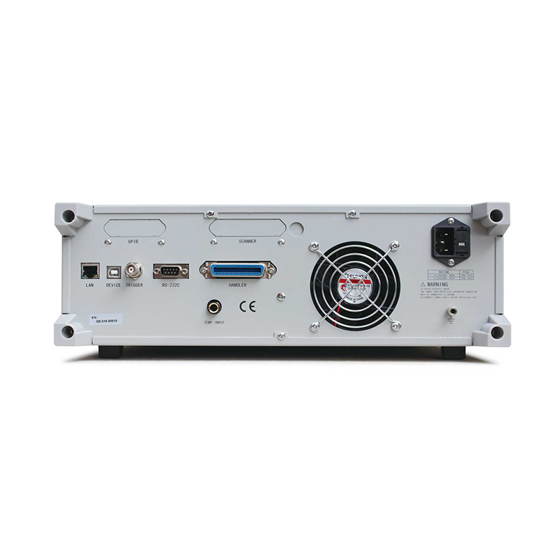
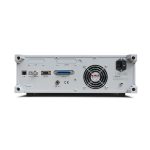
| connector | |||||||||
| USB HOST port | Universal Serial Bus socket, Class A; FAT16/FAT32 format. USB flash drive storage or barcode scanning | ||||||||
| USB DEVICE port | Universal Serial Bus socket, small Class B (4 contact positions); USBTMC-USB488 and USB 2.0 compliant, female connector for connection to external controllers. | ||||||||
| LAN | 10/100BaseT Ethernet, 8-pin, two speed options | ||||||||
| HANDLER interface | For Bin Staging Signal Output | ||||||||
| External DC BIAS control | Controls TH1778/TH1778S bias current sources, up to one TH1778 + five TH1778S (120A MAX) | ||||||||
| RS232C | Standard 9-pin, Crossed | ||||||||
| GPIB (option) | 24-pin D-Sub port (Class D-24), female connector compatible with IEEE488.1, 2 and SCPI. | ||||||||
■ Test frequency: 20Hz-2MHz, resolution: up to 0.1mHz
■ Basic accuracy: 0.05%
■ Test speed: as fast as 5.6ms/time
■ Measuring principle: automatic balanced bridge
■ High power: signal source 20V/100mA
DC Bias: ±40V/100mA
External DC BIAS bias up to 120A
Independent voltage source: ±10V programmable output
■ High stability and consistency: up to 15 test range configurations
■ High resolution: 7 inches, 800 x 480 resolution
■ Multi-function parameter list scanning
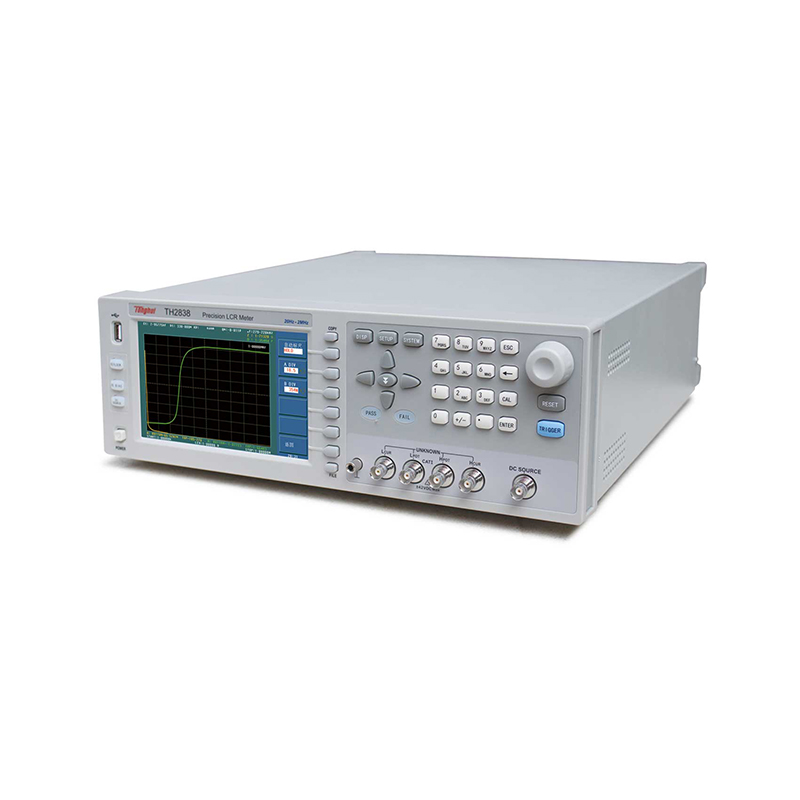
■ Multi-parameter graphical scanning function
■ Automatic polarity function for varactor diodes
■ 10-speed sorting function, sorting results sound and light alarms
■ Storage space: built-in 40 sets of setup files, USB expansion of 500 sets of setup files,
Data log files, image files
▪ Ls-RDCsimultaneous testing
■ High compatibility: Supports SCPI instruction set, compatible with KEYSIGHT E4980A,
E4980AL, HP4284A and other applications
■ Passive Components.
Evaluation of impedance parameters and performance analysis of capacitors, inductors, cores, resistors, piezoelectric devices, transformers, chip assemblies, and network components, etc.
■ Semiconductors.
Test and analysis of parasitic parameters of LED driver integrated circuits; C-VDC characteristics of varactor diodes; analysis of parasitic parameters of transistors or integrated circuits
■ Other components.
Impedance evaluation of printed circuit boards, relays, switches, cables, batteries, etc.
■ Media Material.
Evaluation of dielectric constants and loss angles of plastics, ceramics and other materials
■ Magnetic material.
Evaluation of permeability and loss angle of ferrites, amorphous and other magnetic materials
■ Semiconductor materials.
Dielectric constant, conductivity and C-V properties of semiconductor materialsLiquid crystal materials: C-V properties of liquid crystal units such as dielectric constant and elasticity constant


Capacitance Testing Resistance Testing Inductance Testing
| standard equipment | |||||
| Accessory Name | model number | ||||
| Four ends with card fixture | TH26005C | ||||
| short circuit board | TH26010 | ||||
| Boxed Four-Ended Insulated Locking Kelvin Test Leads | TH26011BS | ||||
| optional | |||||
| Accessory Name | model number | ||||
| Patch Test Leads with Boxes | TH26009B | ||||
| Magnetic Ring Fixture | TH26008A | ||||
| Dielectric Test Fixture | TH26077 | ||||


