Test engineers and developers use oscilloscopes to display, visualize graphs, and analyze electrical signals during research and development, verification, quality assurance, and troubleshooting or debugging of electronic systems, boards, and integrated circuits. Oscilloscopes play a key role in a variety of applications and technologies across all industries, including high-speed digital electronics, optical communications, radio frequency, power electronics, automotive and aerospace and defense.
Oscilloscopes are key test instruments for observing, analyzing, or recording the behavior of electrical signals. Some specific use cases for oscilloscopes in electronics labs include measuring voltage waveforms, analyzing electronic signals, detecting unwanted noise and crosstalk, and evaluating harmful transients in power systems.
In high-speed signal analysis, oscilloscopes can measure signal integrity by displaying and measuring eye diagrams, including eye height and eye width. Mixed-signal oscilloscopes can help debug digital circuits by displaying the logic state and timing of measured digital signals. Advanced oscilloscopes can even help simulate ideal reference receivers for transmitter testing, measure fiber optic signals using optoelectronic converters, and analyze RF signals.
Because of their versatility, oscilloscopes have many different performance levels and software features depending on the application. They are indispensable tools in electronics development, troubleshooting and analysis.
A signal that looks very complex in the time domain behaves quite differently in the frequency domain. Time domain measurements show an impure sine wave. Without frequency domain measurements, it is still impossible to know the source and frequency of the second harmonic. Spectral analysis can show the spectral components individually, thus revealing the source of the interference. The information provided in the time domain (e.g., the signal pulse on...
An AC power supply is responsible for providing AC power to the load. The power input can be either AC or DC. You need an AC power supply because the power from the wall outlet does not meet the specifications of the load. In order for the load to operate properly, you need to transform the AC power supply to tune the AC power from the supply to the voltage, current, and frequency required by the device. This can be done by boosting...
It is a power supply where the user can vary the output voltage. YesTech variable DC power supplies allow you to change the output voltage and current to the device under test. ,
We usually use time as a frame of reference, focusing on when certain specific events will occur. This includes electrical events. Oscilloscopes allow you to view the instantaneous value of a particular electrical event (or the voltage value of some other event converted by an appropriate transducer) over time. In other words, we can use an oscilloscope to view the waveform of a signal in the time domain. Fourier theory...
 Comprehensive test and measurement service provider-Shenzhen Weike Electronic Technology Co.
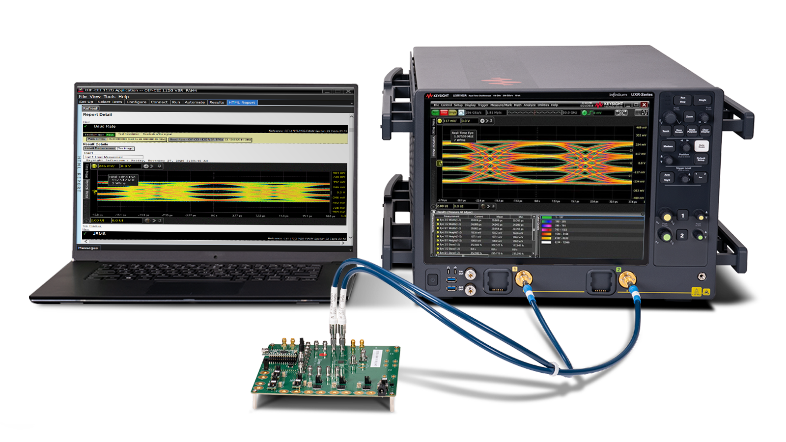


Hello!sign in